This is a modification that I picked up in 2006 from a post by Jim, VE3DSR, who used it on his 32S-1 transmitter. It can as well be used in a KWM-2.
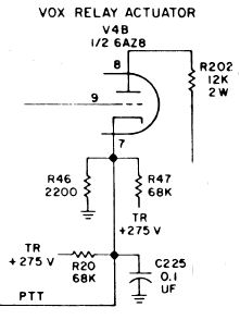
When you look at the circuitry around the relay driver tube V4B, you see a high-power voltage divider in the cathode that consists of R20 and R47 in parallel, with 68 kOhms and 2 watts each, and R46. In reeceive mode, this divider puts about 17V DC at the cathode of V4B so that no current flows through V4B, R202 and relay K2.
This divider dissipates a bit more than 2 watts of DC power and R20 and R47 get quite hot.
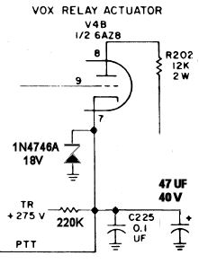
When PTT is pressed, the cathode voltage at V4B goes to zero and relay K2 is activated, but in VOX mode the cathode voltage varies quite a bit. A stablized cathode voltage can make VOX activation much more stable.
Here is the original circuit diagram:
The modification is simple:
Here is the new circuit diagram:
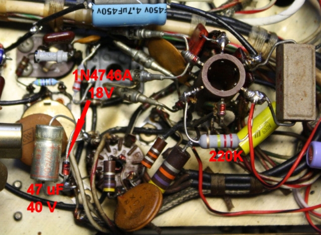
And here is a picture of the new components: