 Idea and Background
 Idea and Background
The idea to produce a standard TV PAL signal using a SVGA graphics card was born a few years ago, where cheap graphics cards with TV output were still not available. To achieve a CCIR conform TV signal with 50 Hz vertical interlaced refresh and 15.625 kHz horizontal frequency on most SVGA cards its possible to re-program CRT timing and generate output signals outside the normal specification range. The following simple TSR DOS programs show these possibilities and provide a solution to connect a computer to a TV set with RGB input using a simple converter that consists of only two resistors. Because the CRT programming is very chipset dependent, every chipset needs its own specialized and optimized program. Currently only a limited number of chipsets is supported:
Chipset/Vendor Mode: 640x480x16 640x480x256
To switch from normal VGA output to TV signal compatible output it is necessary to load the chipset-specific TSR (terminate and stay resident) program at DOS prompt, such as
 How to connect a TV set to the VGA
card output connector...
How to connect a TV set to the VGA
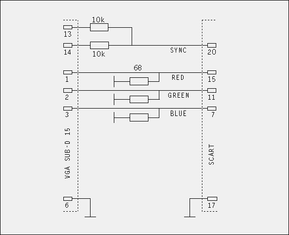
card output connector...Attention !!! Between computer and TV equipment may be a voltage potential difference of several hundred volts, which may damage electronic components. Please rather put some effort on ground level voltage equalization if you do not want to risk a circuit damage. If your TV set is equipped with a SCART socket, you can build a very simple VGA <-> TV connection circuit. It is shown in the picture below. In some rare cases a special activation of the SCART RGB input is needed using a switch voltage of approx. 12V on pin 8.

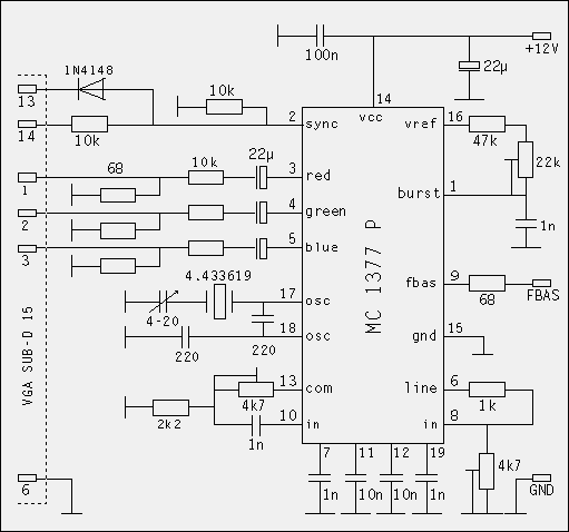
Another method has to be considered if a CVBS signal is required. A very simple version is an integrated RGB -> CVBS converter, as in the following example.
 A ready PCB is available for approx. 10 DM from
The main advantage of this PCB design is its flexible RGB input level adaption circuit, which makes it possible to connect various video sources. For further information please consider the article in the German journal "Funkamateur" from November 1990 (see References).
 Some Technical Details...
The VGA->TV converter consists of approx. 250 assembly language code lines. Its main function units are chip detection, TSR control and interrupt service routine which is the most important part. It is plugged into video subsystem software interrupt 10h and observes every mode switch procedure. If one of the above mentioned modes is activated, TV video timings are are adjusted according the following steps:
 Source code
The project is quite obsolete meanwhile, since VGA adapters delivering a high quality TV signal became affordable in the last years. There will be no further development on support of new graphics chipsets. The source code is available anyway, you can consider it as a programming example of the VGA card registers/functions. The source code can be downloaded here: vgatvsrc.zip. It assembles fine using stoneage Borland Turbo Assembler for DOS.
 References
 Comments, Suggestions:
 [email protected]