 Idea and Background Idea and Background
The plate voltage switch-on AC current of a tube power amplifier can be quite high because of the transformer's low initial impedance and low resistance of the capacitor block on the DC high voltage side. For a short period of time, the transformer, the rectifier and the electrolytic capacitors are enormously stressed. This may reduce the life time of these components.
The Solution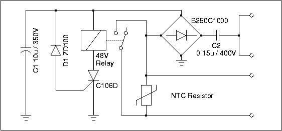
The basic idea of a soft-start circuit is to put a power resistor in series to the transformer, which limits the peak current. After some time, when the transformer's magnetic flow is established and the capacitors are pre-charged, the resistor is short-circuited. The operation principle of the shown circuit is relatively simple. Two of the main design goals are a long delay and a short recovery time. The latter one is however not very critical, since you normally do not on/off-cycle your plate voltage in short intervals. The delay time depends on the capacity of C1, the capacitive resistance of C2 and the zener voltage of D1. On startup, C1 is charged to 100V, then the thyristor becomes conductive and the relay short-circuits the current limitation resistor. Meanwhile, the voltage at C1 has dropped to the normal operating voltage of the relay (40-60V). The recovery time is affected by the capacity of C1 and the coil resistance of the relay. As you may have already found out, the capacitive resistance of C2 (21k at 50Hz) is 4 to 5 times higher than the relay coil resistance (4 to 6K). Thus, the delay time is approximately 4 to 5 times longer than the recovery time. To further improve this ratio, the thyristor switch voltage was increased to 100V. With the given component values a delay time of more than 500ms and a recovery time of less than 100ms can be achieved.
Comments, Suggestions: [email protected]