 The K3 and K144XV Combo
 The K3 and K144XV Combo
For some years I own an Elecraft K3 transceiver which works very well. My K3/100 is a ready built unit (S/N 2819) which I've bought second hand from a good friend. I mainly use it for portable operation during VHF contests in conjunction with a Kuhne Electronic TR144H transverter. This combination is unbeatable in terms of reliability and large signal capability. However, the TR144H is almost as big and heavy as the K3 itself and draws a lot of power. Thus, I've decided to try the K144XV transverter which completely fits into the K3. Of cause, the K144XV does not achieve the performance of the TR144H, but for battery powered portable operation on 144MHz as well as for using the K3 as a microwave band IF rig it might be very useful. And most important, the receiver performance of the K3/K144XV combo is far superior compared to most other transceivers with integrated 144MHz capabilities.
 K144XV Circuit Design
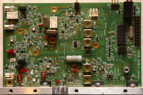
The K144XV is essentially an Elecraft XV144 transverter adapted to fit into the K3. The RX and LO parts are almost completely taken over from the XV144 so you can expect a similar level of RX performance from the K144XV. Contrary to the XV144 the TX/RX switching inside the K144XV is implemented by using PIN diodes, which is smaller, faster and not really a drawback in terms of IMD. To further reduce the K144XV size the TX driver and final amps have been completely replaced by discrete stages rather than using a RF module as in the XV144. The design of these high gain discrete power stages under space constraints can be a challenging task, since unwanted coupling between components might cause oscillations. As there are no dedicated control lines connected to the K144XV, the transverter functions are handled by the KXV3A interface via DC voltage levels and pulses on the IF in/out lines. TX/RX switching is maintained through an overlayed DC voltage on the receiver IF line, whereas the transverter ON/OFF and LO range control is managed through different length DC pulses on the transmitter IF line.
 K144XV TX Problems
 Modification Procedure
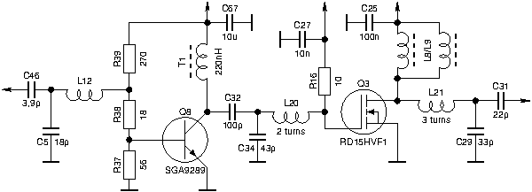
You should be familiar with SMD component handling when doing this modification. Following replacement components are required: 10 Ohm 0805, 18 Ohm 0805, 56 Ohm 0805, 270 Ohm 0805, 100 pF 0805, 22 pF 1206, 33pF 1206, and a 220 nH inductor with axial leads and sufficiently high SRF (> 300 MHz). Dismantle the transverter completely and remove the following components: L2, C97, C98, R29, T1. Replace C32 with 100 pF, R37 with 56 Ohm, R38 with 18 Ohm, R39 with 270 Ohm, and R16 (back side) with 10 Ohm. The 220 nH inductor is mounted vertically through two of the four holes of the former T1 location. Chose the two holes towards Q8 for inductor installation and short the other two holes with a piece of wire. Replacement of C29 with 33 pF 1206 and C31 with 22 pF 1206 completes the SMD work. In a second step the inductors L20, L21 have to be changed (reduced number of turns) according to the schematics below. Fine tuning of the TX is required by squeezing/pulling these three air coils until maximum output power has been achieved. Don't touch the other air coils !
After re-tuning has been completed these modifications result in an increased TX stability and no oscillations can be observed anymore at any power/frequency. Component alignment has also been found less critical after modification. Output power has been measured at 9.5W. This is sometimes already too much for many microwave transvertes. It is therefore a good idea to drill a hole into the top cover to reach the TX gain setting (R87) without opening the transverter. Please note that this description reports only the test result I've obtained from my own transverter. The results have not been verified by Elecraft or any other K144XV users. The K144XV Modification

 Comments, Suggestions:
 [email protected]