| Design principles | 5-El.-2-m-OWM-Yagi | 8-El.-2-m-OWM-Yagi | 8-El.-2-m-OWL-Yagi | 11-El.-2-m-OWL-Yagi | 14-El.-2-m-OWL-Yagi |
The redesigned 8LFAD with a simple 12,5-Ohm-Dipole or a Folded Dipole
This Yagi was developed to look if the 8-El-LFA of G0KSC could be built without the LFA-loop as a simple Yagi with an open or a folded dipole. This design by Justin has one of the best patterns I have ever seen for a Yagi. The result with the split dipole is as good as the mechanical more complex LFA-loop. It uses the design rules for radiation centre of the OWL-Yagis of G0KSC, look here: G0KSC-OWL The LFA-loop is a 1:4 transformer and the intrinsic impedance of the Yagi is 12,5 Ohm. The radiation pattern of the loop is not identical with that of a folded dipole, that means the loop is not the same as a folded dipole but the match characteristic is 1:4, too. Therefore some changes in the radiation centre were made with surprising results. If you use a folded dipole it should be mounted exactly symmetrical, that means the two parts of the dipole must have the same distance to the elements plane. |
|
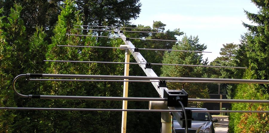
The Yagi built with the exact dimensions predicted by AO and YO by K6STI, without any tuning. The elements are 5 mm, the holders are a special model of SM7DTT. Tnx to Sven, SM7DTT See the SWR <= 1,1 with a bandwidth of 1 MHz below. |

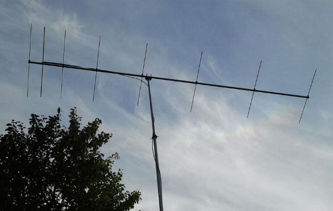 |
The 8LFAD with an open dipole and the 12,5-Ohm-DK7ZB-match built by Andy, SP3IYM He reports about a very good low SWR bandwidth and good receiving results. He used the given lengths of 8-mm-parasitic elements with the black Polyamid- holders and a 12-mm- radiator without any tuning! |
 |
Gain 11,0 dBd (13,15 dBi) F/B 27 dB Boomlength 3,75 m The Yagi can be built with open or folded dipole. If the folded dipole is to be used the more mechanical complexity must be decided by the builder. You can match the Yagi with the 12,5/50-Ohm-DK7ZB-match (do not believe in any mysterious matching loss in the cable, but use good quality coax- cable!) |
In this Yagi you see the concepts of three different design principles: YU7EF: Director chain for a maximum suppression of the sidelobes in the azimuth and elevation plane G0KSC: The extrem narrow spaced driver cell of Ref, Rad and Dir 1 for great bandwidth and good F/B ("OWL-Yagi") DK7ZB: Low-impedance 12,5-Ohm-principle for Yagis for the easy DK7ZB-match or 50-Ohm-folded dipole I must remember that the method of feeding a low impedance 12,5-Ohm-Yagi with a folded dipole I had described in 1999 was used before in the 70ies by TONNA with his legendary 6,5 m long 16-Element-Yagi and 75-Ohm-direct-feed. |
 |
 |
 |
In the 3D-plot you can see the outstanding pattern of
this Yagi with a simple 12,5-Ohm- Dipole!
For your own investigation you can download the EZNEC-File here: |
Elementpositions
| Ref | Rad | D 1 | D 2 | D 3 | D 4 | D 5 | D 6 |
| 0 mm | 170 mm | 430 mm | 860 mm | 1460 mm | 2190 mm | 2985 mm | 3730 mm |
Elements 6, 8 and 10 mm, Radiator 12 mm
| Diam. | Ref | Rad (12 mm) | D 1 | D 2 | D 3 | D 4 | D 5 | D 6 |
| 6 mm | 1024 mm | 974 mm | 963 mm | 940 mm | 920 mm | 896 mm | 864 mm | 831 mm |
| 8 mm | 1022 mm | 974 mm | 957 mm | 933 mm | 912 mm | 887 mm | 854 mm | 820 mm |
| 10 mm | 1020 mm | 974 mm | 953 mm | 927 mm | 905 mm | 879 mm | 846 mm | 811 mm |