Wireman-J-Poles

The Vertical Sloping Dipole

The CE0Y-7-m-Triple-Leg

Vertical 2x7m-Double-Zepp

The Battle-Creek-Special

The C-Pole Vertical.-L

J-Pole antennas for 2m-40m with Wireman-cable (DK7ZB)

(a J-Pole with 300-Ohm-Twinlead for 145MHz see down)

Rate this site


(with 10 = top)

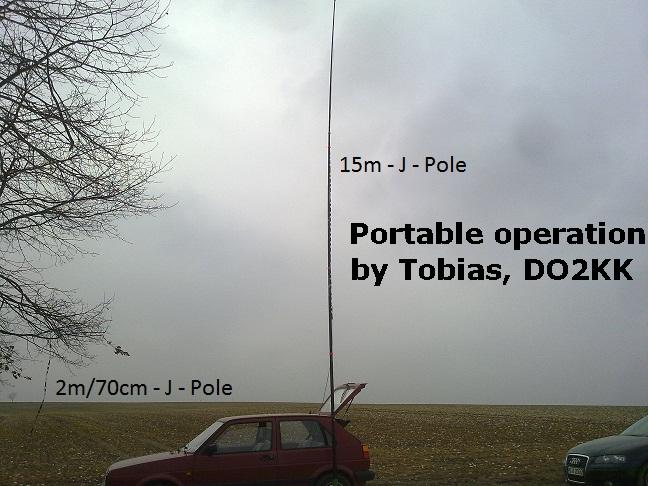
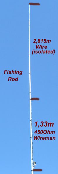
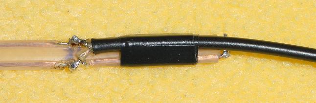
The picture shows the scheme of a J-Pole antenna. The high impedance feeding point of a lambda/2-wire (L1) is matched from some KOhms to a low impedance with a  lambda/4- matching sector (L2).

The point XX has an impedance of 50 Ohm for direct feed with a coax cable. XX is  symmetrical, a choke or balun could be useful to avoid sleeve waves on the screen of the coax.

A very simple method for the  lambda/4-part is to use a 450-Ohm-Wireman cable. 

I have built up the antenna for 2 m, 6 m, 12 m and 30 m. The table gives the values for experimenting with the other bands.

L1=0,471 lambda  (Halfwave-Radiator)   L2=0,223 lambda  (Wireman-cable)    

Solder the braid of the 50-Ohm-coax at the right X, the inner conductor to the left X. XX about 5-10% of L2.

The antenna can be mounted in several ways:

The classic J-Pole with both sections mounted vertically.

Length 3/4-lambda,  only for the higher bands.


It is no difference in the radiating conditions, if the lambda/4-part is vertical or horizontal.

The pattern is identical with a vertical dipole.

Both parts horizontally mounted

The "Zepp"-configuration

The antennas were tested on 2 m, 6 m, 1 2m and 30 m. The lengths for the bands marked with "*" have not been tested, try with he given dimensions. For other frequencies use the following formula for insulated 2-mm-wires for L1. Not-insulated wires need a longer L1-section.

The points X-X are 5-10% from the shorted part of the Wireman-cable (look for best SWR).

For the 50MHz-J-Pole look on the special page:   50MHz-Halfwave-Verticals

Band

l/2- Wire  (insulated)

l/4- Wireman  V=0,905

XX

Fo MHz

SWR

Bandwidth SWR<1,5

40m*

20,02 m

9,46 m

73,0 cm

7,05

-

100 KHz

30m

13,96 m

6,61 m

58,5 cm

10,12

1,1

150 KHz

20m*

9,98 m

4,73 m

35,0 cm

14,15

-

200 KHz

17m*

7,80 m

3,70 m

26,5 cm

18,1

-

250 KHz

15m*

6,66 m

3,15 m

22,5 cm

21,2

-

300 KHz

12m

5,67 m

2,67 m

18,5 cm

24,91

1,0

350 KHz

10m*

4,96 m

2,45 m

15,5 cm

28,5

-

500 KHz

6m

2,815 m

1,33 m

6,5 cm

50,15

1,1

1000KHz

2m

97,5 cm

47 cm

3,5 cm

145,2

1,0

1500 KHz


The Wireman-J-Pole during the DXpedition of Tom, DL2RUM as FS/DL2RUM


The result of 10 Minutes work with the 12-m-J-Pole, mounted on a fishing rod:


SWR > 1,3

21,1-21,3 MHz


The 50-MHz-J-Pole

see:

50-MHz-Verticals

horizontal rule

J-Pole with 300-Ohm-Twinlead for 145MHz

The J-Pole for VHF and UHF constructed with 240-Ohm- or 300-Ohm-Twinlead

The lengths are for 145 MHz and 435 MHz. The 2-m-J-Pole can be used on 70cm, too with an SWR <1,6.

SWR 145-146 MHz <1,5

SWR 430-440 MHz <1,6

The dimensions of A, B and C are in the table below

Attention: The mounting in a plastic pipe or with tape on a fishing rod will detune the antenna to lower frequencies and needs a little bit of correction!

horizontal rule

Lengths for the bands 2m and 70cm

Band

A

B

C

145 MHz

137cm

42cm

30mm

435 MHz

45,7cm

14cm

20mm

horizontal rule

The connection of the RG-178 coax cable, here 240-Ohm-TV-wire

horizontal rule

The same construction with 300-Ohm-wire. The cable is available at  DX-Wire

horizontal rule

The cut piece of wire between the parts A and B at the right side of the J-Pole

horizontal rule

The 2-m-J-Pole ready for use

At the top is a hole for a rope. The antenna can be mounted in a tree or any other support.