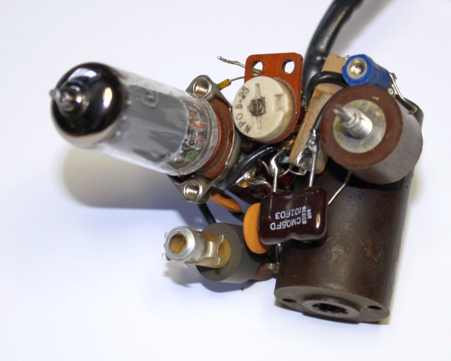
The guts of the PTO with the new C302, ready to oscillate.
The other day, when I switched on my KWM-2, the 100 kHz calibrator had quit working. I immediately tried the usual measures like tapping the Xtal and swapping V12. No result. I went on to check the receiver and it did not take long until I realized that the calibrator was indeed working perfectly - only the frequency scale had moved by 30 kHz.
A few weeks ago I had re-lubed the PTO, so could I have forgotten to fasten the set-screws? No, the dial drive was smooth as it should be and the end-points did not move at all.
Finally a check with my counter connected to J18 quickly revealed that the whole PTO frequency range had shifted upwards by about 30 kHz. I routinely swapped V301, but then soon realized that a 30 kHz shift upwards was equivalent to a loss of about 70 pF in the tuned circuit, too much for the influence by just tube capacitance.
Then a nasty thought came to my mind: when I had opened the PTO, could I have damaged one of the small and unobtainable mica capacitors C301 with 20 pF or C305 with 100 pF ? I had to take a look, but naturally I didn't want to take the whole PTO assembly out again. So I removed the rear mounting bracket just far enough to get access to the innards. Tapping on the small capacitors didn't change much, no loose connections or broken elements were identified, only the quite stable shift of 30 kHz. That meant I had to do it, take the PTO out again and then remove all the parts from inside the box.
I would not have done this without the excellent article(*) on PTO repair by Jim Miller, N4BE. As he suggests, it is indeed quite easy to squeeze the PTO "guts" out of the box and have them on the table for inspection. When you connect a suitable power supply and insert the tube, the assembly even oscillates as it should, even without the core inside the tuning coil. Interesting to note that without core the oscillating frequency is only slightly above the highest nominal working frequency. In my case the PTO on the table ran at about 2.78 MHz.
I used an old tube-type bench supply (similar to the Heathkit IP-17) with widely variable high voltage. After first trying some of the standard procedures like tapping and applying cooling-spray with no definite result, I started rocking the high voltage adjustment. After a few trials I had a reproducible result: starting the cold PTO with 100 V supply gave a lower frequency output. Increasing the supply voltage above about 130 V let the PTO jump up by about 30 kHz. At about 150 V supply the frequency was extremely sensitive to variations in supply voltage. It changed as much as 50 Hz/V or 2.5 kHz for a 50 V change.
So there must be a frequency-determining element in this PTO that is sensitive to supply voltage. Capacitors C306, C309 and C310 are directly connected to the supply voltage and Jim Miller suggests to replace them. So I started working here. I took out one by one and replaced them with new ones while watching the frequency. No change, I did not see that these capacitors had any remarkable influence on frequency or stability. At least replacing them did not solve my problem.
Now only the direct elements of the tuned circuit were left. I did not suspect the tuning inductances, and the small capacitors reacted normally when treated with cooling spray. That left the two larger capacitors C302 (1000 pF) and C303 (3000 pF). Jim Miller suggests to replace C303, but that capacitor was deeply hidden in the PTO wiring while C302 was easily accessible and there seemed to be some erratic reaction to cooling spray.
So I figured there was a 55% chance for C302, took a deep breath and cut one of its leads. I had a small 1000 pF styroflex (polystyrene) capacitor at hand and put that in, flipped the switches and ...
Success! I again had a stable PTO on the right frequency that was no longer strongly sensitive to voltage changes, only by about 2 Hz/V or 100 Hz for 50 V change. I could have left the PTO that way, but polystyrene capacitors are not designed for higher temperatures, so I looked around for a 1000 pF dipped mica. After that arrived I was able to reassemble the PTO and to mate it once again with my KWM-2. I do not have notes on stability figures before the fault appeared, but my impression is that the stability is much better now. Excellent indeed.
What may have been the cause? Well, there was no direct influence of DC supply voltage, but with increasing supply voltage the RF voltage in the PTO circuit also increases. Very probably the 1000 pF mica capacitor C302 had established an internal fault that not only reduced its value but also made the remaining value strongly dependent on the level of applied RF voltage.
The guts of the PTO with the new C302, ready to oscillate.
* http://www.collinsradio.org/70k-2-stability-service/