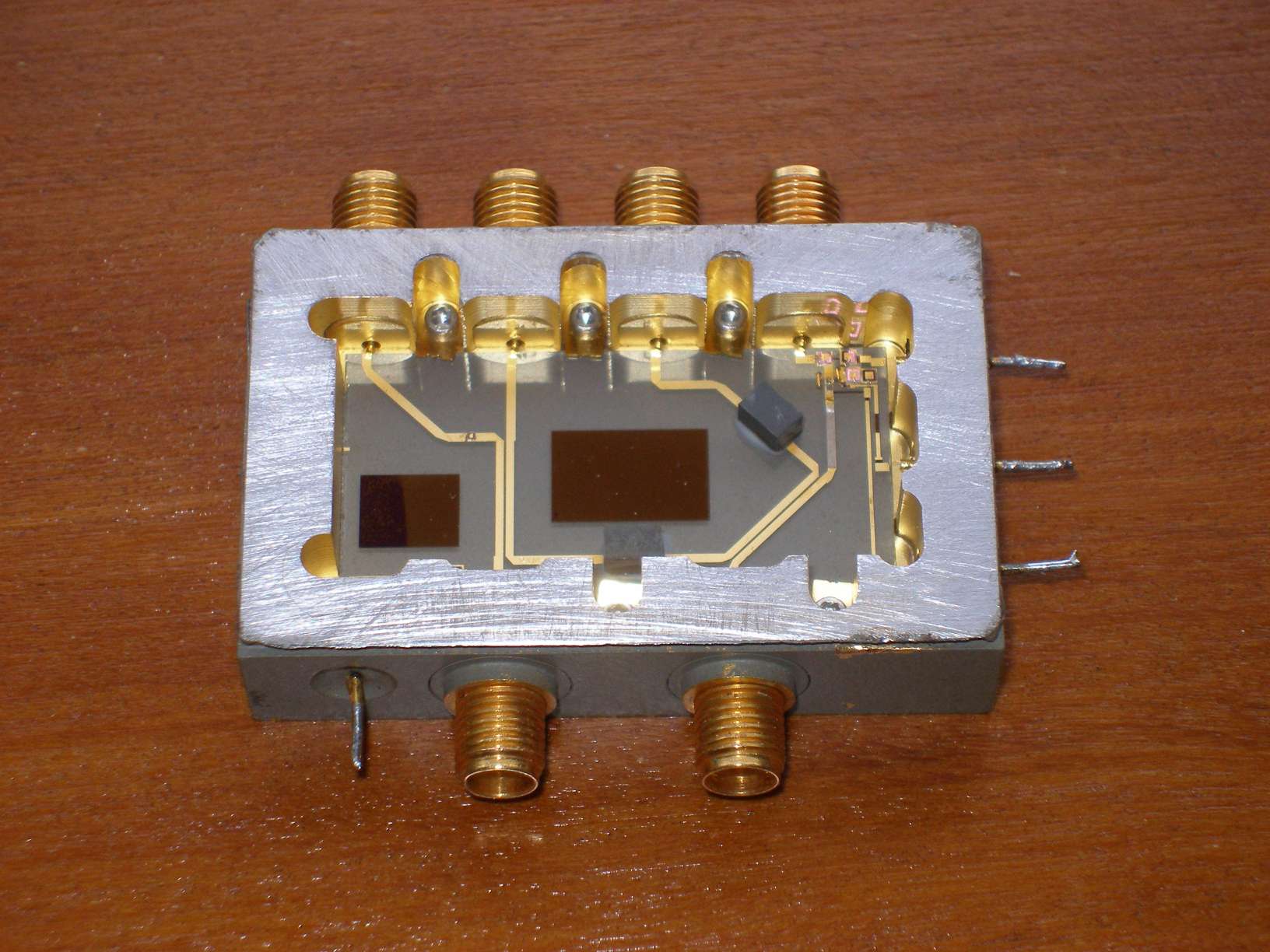
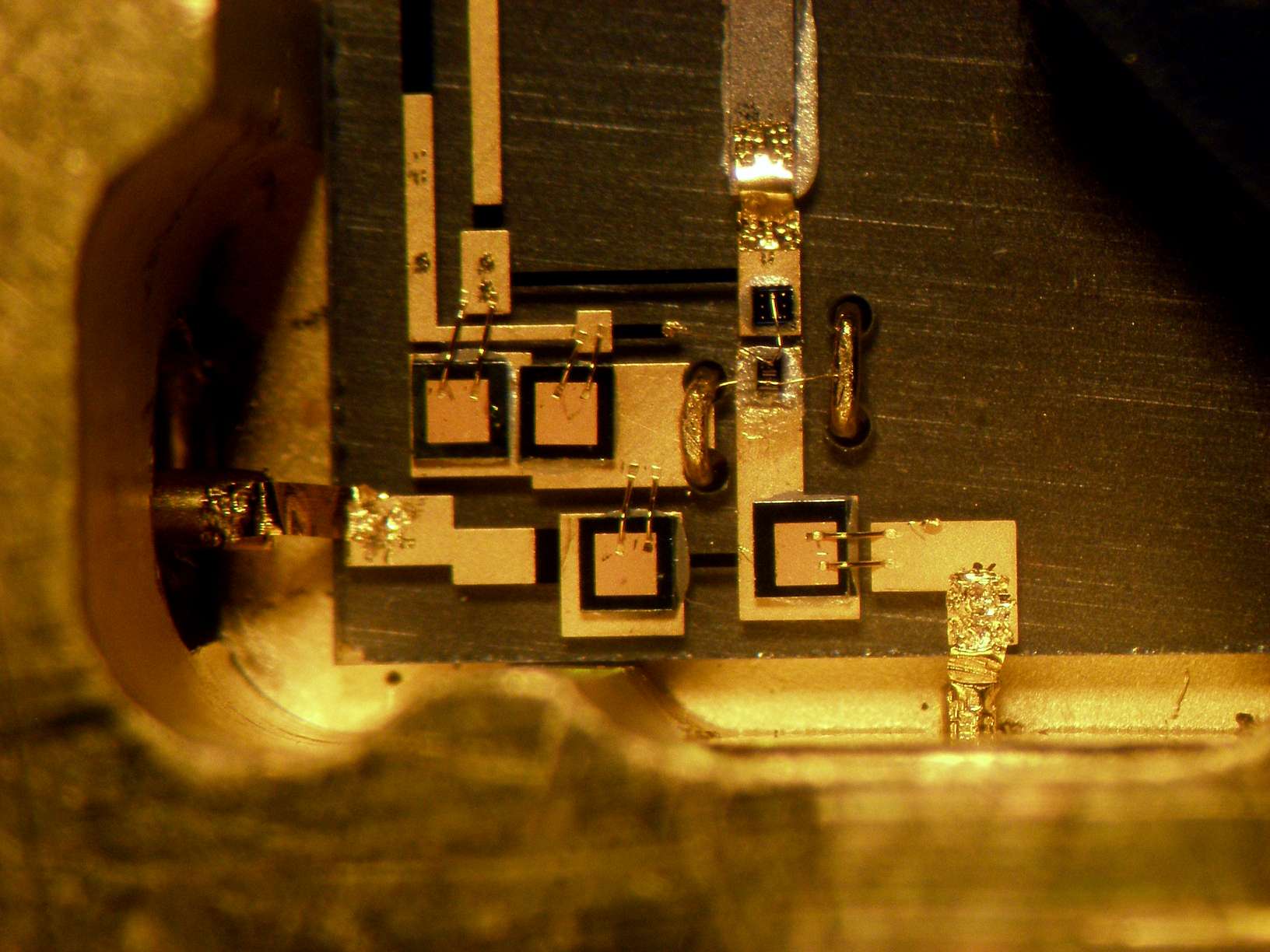
On these HP mixers very few have just the diode destroyed, the vast majority has both diode and IF bipolar transistor destroyed.
Here you see one mixer where a new transistor was applied and its input bonded to a new diode junction.

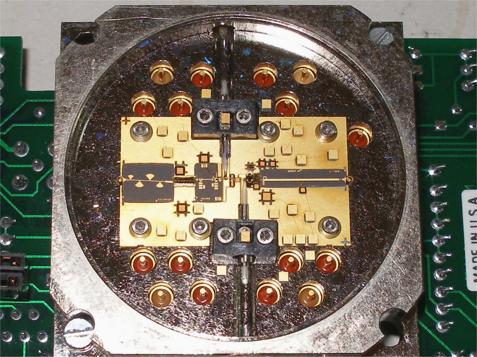
Some Wire Bonding...
HP spectrum analyzer frontend mixers.
|
Spectrum analyzers Mixers are the number one on the top list of user
destroyed devices (by far). On these HP mixers very few have just the diode destroyed, the vast majority has both diode and IF bipolar transistor destroyed. Here you see one mixer where a new transistor was applied and its input bonded to a new diode junction. |
|
|
|
An YIG oscillator from a TEK 492/4/5/6 spectrum analyzer.
|
This oscillator had a defective output amplifier and produced less than 0dBm output
power with a lot of ripple. Here you see the output GaAs FET replaced by a more recent Harris HMF33000 (the original was a non cataloged (AFAIK) Avantek type that resembles a lot like a more recent version of the on the historical TC300 from HP). Die attachment was eutectic and all wirebonding were done with my homemade wedge bonder. On the right you see a close-up of the replaced FET. |

|

|

|
When the big ones goofed, YIG from a TEK496P.
|
This oscillator had a defective output amplifier that was repaired as on the example above. However I noticed that the output FET had excessive drain supply and that was the presumable reason for its original failure. Looking for the cause I discovered the voltage regulator (a 7808 in die form) had a missing wirebond ground connection. It was clearly missing but not because it was evaporated or got lost, it is beyond any doubt that this connection was never there as both the chip pad and the gold substrate have no signs of any wire ever being attached. Only visible mark is a one time probe needle contact, the same as on all the other IC pads. Needless to say that this voltage regulator has no gnd on the back side of the chip, furthermore all Avantek YIGs I opened so far have the 3 connections on the regulator chip as required. Clearly Avantek goofed on this one... at least quality control did. I just wonder how the output FET survived that long with about 11.8V on drain instead of the 6V that should have been present there (the FET has an Absolute Vds maximum of 8V trusting the datasheet). |

|

|
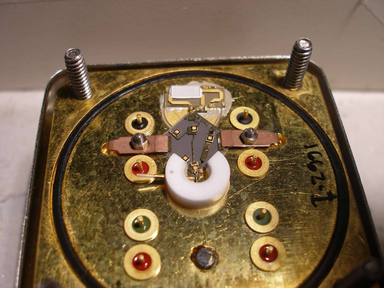
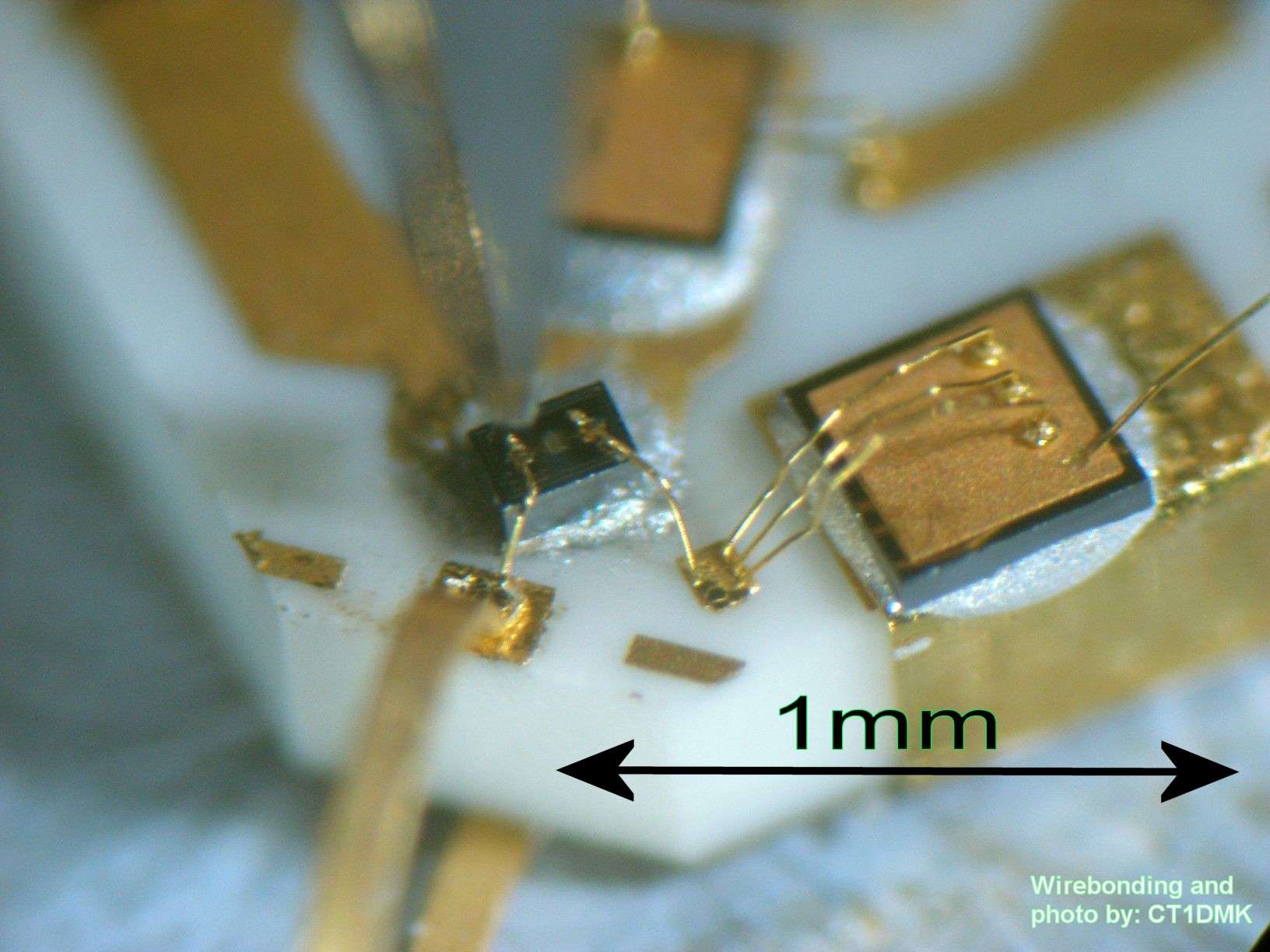
YIG oscillators from HP856x's/HP70000's spectrum analyzers and alike.
|
I have seen many of these YIG oscillators fail. They exist in several different HP analyzers
as many models employ the same or very similar oscillator, even
if they have a different HP ref number all end up to have exactly the same
oscillator hybrid circuit inside (despite some variations on the bias/alc board). All of them, without exception, have a failed oscillator transistor being all the rest perfectly ok. Sometimes the transistors still looks good in DC but strangely the chip seems to have developed some kind of moist on the bonding pads and they got corroded away. It is indeed a puzzling semiconductor failure. Here you see a new transistor applied. Last picture on the right is a close-up of oscillator section while the substrate was sitting on the hot work-holder of the bonding machine, picture taken right after it has been wire-bonded. |

|
|

|
|
RYTHM - YIG Tunned Harmonic Mixer from HP856x's/HP70000's spectrum analyzers and alike.
|
On the top list of most difficult job ever are the RYTHM mixer and preselector modules
from the 26GHz spectrum analyzers. Interesting enough it was not even a wirebonding
job although I had to disconnect things while looking for the malfunction. The circuit looked absolutely pristine and never touched after factory albeit all YIG spheres were at very uncommon positions (see pictures) while the supporting rods still had the fixing drop of gray epoxy glue placed at factory. When I had exhausted all possibilities I decided to retune all sphere positions and rotation trying to find and improvements. It was noticed immediately that spheres were indeed grossly misplaced. Then I had went through an over 100 hours tuning effort to get it within specs (or even better than last calibration specs as I ended up with 1dB to 2dB above level readout on the SA). If you understand the effort of adjusting a filter with 4 cavities where both center frequency and coupling and Q is adjustable, now imagine the same but with all cavities being tuned over a broad frequency range and adjustments being done under the microscope adjusting microns on position and rotation leveling and magnetic field asymmetry, in trial and error steps as some of the tuning could not be done with the assembly closed, and with assembly open you have no magnetic field circuit. This required a setup involving a network analyzer and a trick to bypass the mixer section, or alternatively a current sweeper for the coil two signal generators a power meter and an oscilloscope displaying in X/Y mode. To be explained remains how the YIG spheres got displaced so evidently over the years. The best explanation so far is that a minute nanometer drag happens on each temperature cycle that accumulate over hundreds (if not thousands) of temperature cycles caused by user on/off operation cycles. |

|

|

|
Dual YIG oscillator (HP) wide band coverage from 2 to 20GHz.
|
This is a more modern design, already incorporating MMIC amplifiers on both oscillator sections. The low band uses a bipolar transistor to cover 2 to 11GHz which is an extremely wide coverage for a bipolar oscillator, followed by a wideband TWA (traveling wave MMIC amplifier). The high band uses a GaAs FET that in this case is the input FET of a standard MMIC amplifier ...interesting design. This one had a problem on the low band oscillator section. A small deterioration in YIG sphere properties resulted in slightly less Q on the lower frequencies that was enough to stop the oscillation at bottom frequency range. Replacing the YIG sphere followed by extensive retuning brought it back to life over the full operating range. |
|

|
Broad band amplifier 2-22GHz (26.5GHz) from a HP sweep generator.
| This job turned out to be quite interesting as the original TWA (traveling wave amplifier) chip could not be sourced at a reasonable price. However replacing it with a Celeritek or Hittite chip proved to be possible after considering the similarities in chip performance and supply voltage and bias. A Celeritek chip was applied and the results were excellent (as good as original or even better). Note the Celeritek chip is slightly smaller than the HP original and some care was needed to make a connection to the chip without adding to much deviation from the 50OHm impedance potentially critical issue at the top of the frequency range (26.5GHz). This was achieved by using a ribbon connection to the chip that was tapered to match the chip bonding pad. |

|

|
YIG tunned multiplier 2-26.5GHz from an HP signal generator.
|
The YTM from the HP 867x series I've seen all had a destroyed YIG coupling loop on output circuit.
Apparently some condition seems to inject DC into the YTM. New coupling loop was applied and this case is not simply a wirebond connection as it needs to respect not just electrical connection but also loop size shape and position. |

|

|
Another HP YIG tuned multiplier 2-26.5GHz with integrated driver.
|
The YTM from one of the more modern HP 867x sweepers very similar to the above YTM
but this one has an internal amplifier to drive the multiplier diode. The MMIC has two identical amplifiers that are coupled externally and used in phase. The output FET of the left amplifier failed and the YTM start producing amplitude noise on the output signal. This MMIC is marked TC519 and I could not identify this in any HP catalog or data-sheet. Many MMICs carry a "TCxxx" marking and a correspondence to a commercial "AMMC..." reference can be found. Repair consisted of replacing this TC519 MMIC with two CMM09 amplifiers from Celeritek in order to maintain the RF layout as original as possible. |

|

|

|
Tek. 492/6 spectrum analyzer frontend mixers.
|
These mixers had a rework done using a gap-welder to attach the beam lead diodes and
to attach the ribbons that connect the quartz substrate (or alumina, on recent models)
to the soft-substrate that connects to the mixer main body. Here you see several stages of the workout. |

|

|

|

|
A nice MMIC amplifier (17dB / 6-18GHz / p1 18dBm).
| This amplifier uses an HMMC5618 MMIC from HP and both assembly. The milled alu case was homemade. Substrate pieces and 50 ohm lines were recovered from old and incomplete hybrid assemblies I obtained surplus. |

|

|

|
Yet another amplifier stage with the AMMC5618.
|
This stage of amplification (of a multi stage amplifier/equalizer) was made on a soft substrate,
rogers RT5880, where the MMIC was placed on a pad with sixteen 0.2mm metalized vias to GND.
This pad has low inductance to the substrate GND and has also enough thermal conductivity to
the Alu box where it is assembled. The chip input and output pad become considerably higher than the tracks and that would require longer wirebonds. To achieve low inductance from the MMIC to the 50Ohm tracks gold blocks with the same height of the chip were used making the connection leveled and shorter and two bond wires with low loop height were used. Good performance as obtained with the maximum frequency exceeding 19GHz that appears to be solely limited by the MMIC characteristics. |

|
Any comments:
 Luis Cupido