ANTENNAS! BUY OR BUILT?
ANTENNAS! BUY OR BUILT?
![]()
|
|
|
|
|
|
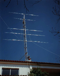
CT1BWW & CT1AHU WITH KLM KT34 OF LUIS CT4NH |
CT1BWW & CT1EGW WITH 10ELEMENT SOMMER ANTENNA ON NELSON,CT1KT QTH |
CT1EGW AND CT1BWW WITH C3 FORCE 12 OF CT98EXPO (Last World Exposition of the 20 Century) |
CT1BWW & CT1AHU WITH C4 FORCE 12 OF MARQ |
|
|
|
||
|
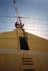
CT1BWW & CT1AHU WITH A4 CUSHCRAFT AT REP HEADQUARTERS IN LISBON |
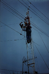
CT1BWW ON TOP TOWER AT S05X WESTERN SAHARA DX'PEDITION |
||
 |
 |

|
|
|
CT4NH, LUIS WITH CT1EGW & CT1BWWW WITH KLM KT34 OF LUIS |
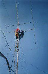
CT1BWW,CT1EGW,CT1AHU AND CT1FIJ WITH ANOTHER C4 FORCE12 |
CT1BWW,CT1EGW, WITH OPTIBEAM ANTENNAS MARQ |
CT1BWW,ON HIS TOWER AND OPTIBEAM ANTENNAS |
|
|

I don't want to explain what everybody already
knows about antennas, for myself all antennas are good!
But I just
want to explain Why I decide for Opitbeam! I've already work with
Cuschcraft, Force 12, I've already help mounting over 30 antennas from
other friends. So !I know very well different manufacturers.
I choose Optibeam for following:
I want to have a antenna with a good VSWR and should work from 10 to
20 Meters including WARC Not too Heavy and with NOT A LONG Boom. (This is because my tower is
not Telescopic and it's supported by stream steel cables.(I've to put
a J-Pole to setup all antennas)
OPTIBEAM 9-5 The Antenna Technical features exactly as showns on the
WEB-Page .
My location as very problematic strong Winds from Atlantic Coast. Antenna made under German Techonoly as Very Good Quality. (ask for others OPtibeam Users if you have any doubt!)
That I've decide to have 40 Meters Band I've to buy 2 antennas OPTIBEAM 9-5 and a second antenna for 40 Meters OPTIBEAM 1-40, I study very carefully with my Budget. OPTIBEAM as Very Good Prices comparing with others.
I'm accustomize with mounting antennas and towers , but I decide to ask to OPTIBEAM some advise about to have two (2) antennas on same mast .They give me VERY Good Support from Factory.
What I Expect on the antenna? First QSO on 20 Mts (BS7H Phone) Phone after a while (BS7H CW). Work DXs easy on WARC and also very good VSWR curves. You don't need POWER !
Usually I'm saying I prefer 2 elements
without traps than 3 elements with Traps. Nowadays more important ARE
NOT TRANSMITTING but have a GOOD RECEPTION, GOOD LISTENING.
On the same mast about 2,5 Meters I have my OPTIBEAM 1-40
This antenna SYSTEM are REALLY WHAT i EXPECT!
If you hear me give me a call ! I'm using a OPTIBEAM !


![]()
![]()
all I Make It?L. B. Cebik, W4RNLThose of us with more time than money get the urge to upgrade our antennas from dipoles to beams in the home workshop. The logical first step might be a 2-element Yagi. Often, we skip this step because we have heard or seen evidence that 2-element Yagis do not quite have the specifications we want. If we make use the common reflector-driver design, the gain is low and the front-to-back ratio is poor. If we opt for a driver-director design, we get more gain and better front-to-back ratio, but a very narrow beam width and a potentially very low feedpoint impedance. So we immediately jump to 3-element designs. Our next step is usually a semi-fatal one. We search the magazines and handbooks on our shelves for a design that looks like one we can build. We know what the author claims the beam will do, but we are not ever sure of how it does what it is supposed to do or whether our version is doing the same thing. So let's back up a bit and look at some 3-element Yagi basics. I shall focus on monoband beams, because they are much easier than multi-band beams to model and to build so that their performance matches the model. Even if you have your heart set on buying a tribander, perhaps these basics will help you better to understand both the antenna maker's claims and the performance you actually get. The basics I have in mind have little to do with the theory of parasitic element operation. The ARRL Antenna Book and some references I shall mention along the way do a good job at that level of explanation. Instead, I shall begin in the middle of things with some distinctions among Yagi designs. There are so many Yagi designs floating around today that they can be at first sight a bit bewildering. High Performance Designs The first decision we have to make is whether we wish to have a wide-band Yagi or a high-performance Yagi. Let's begin with the high-performance designs, since these have very great initial appeal. We shall return later to some wide-band designs. Once we have opted for a high-performance design, we have to figure out what we mean by that term. First, there is the matter of size. The element lengths will not vary by a large amount from one design to another (but they will vary significantly in terms of the performance). So, size turns out to be a question of boom length. James Lawson, W2PV, developed most fully the notion that the gain of a Yagi is highly dependent upon the boom length. His book, Yagi Antenna Design, has become one of the classic references for those interested in basic Yagi theory. Based on his work, many designers have optimized 3-element Yagis of various lengths for maximum performance. Maximum performance is a balanced mix of high gain, good front-to-back performance, and a satisfactory feedpoint impedance. Let's work backwards through the list. For almost any length boom, one can get a little more gain from a Yagi by so spacing and sizing the elements that the feedpoint impedance drops to about 10 Ohms or less. Most high performance designs you will encounter tend to opt for feedpoint impedances closer to 25 Ohms. The reasons are many, but one good reason is a matter of losses. Suppose that the total resistance of all the connections at the feedpoint, including those of a matching system for 50-Ohm coaxial cable, amount to 1 Ohm. (That is a quite high value and can be reduced by good construction practices.) With a 10-Ohm feedpoint impedance, about 9-10% of the power is going to heat. If the feedpoint impedance is 25 Ohms, then the loss is closer to 4%. To this consideration, we can add the fact that it is generally easier to design low-loss matching systems for a 25-to-50 Ohm conversion than for a 10-to-50 Ohm conversion. So 25 Ohms becomes a kind of de facto (but not absolute) limit to a Yagi's feedpoint impedance. For the higher feedpoint impedance, it is also somewhat easier to design a 3-element Yagi whose gain and front-to-back performance figures hold up across such HF bands as 20 and 15 meters--as well as the first MHz of 10 meters. As well, the designs can be replicated in the home shop with moderate building skills and are not so finicky as to require industrial laser measuring equipment in setting the dimensions. Within these constraints, then, lets look at three good designs for 3- element Yagis. |
 |
| As revealed in Fig. 1, the designs I
have in mind use three different boom lengths. The
long-boom design, shown for 28-29 MHz, is adapted from an
optimized design by K6STI. It uses an 11.31' boom, which
is nearly 1/3 wl long. The K9EUV design uses a 9.88'
boom, and has the additional feature of using equal
spacing between elements. (A fourth director element at
the same spacing and the same length as the present
director provides good 4- element Yagi performance.) The
third design is a short boom Yagi, also by K6STI, that
requires a 7.5' boom. For construction, you should round
these boom-length numbers upward to the next whole foot
to provide room for mounting plates and hardware. So we
have 12, 10, and 8 foot boom 3-element Yagis. Caution: Do NOT build these designs as given here. They all use uniform diameter elements. Converting them to the actual lengths needed by physical designs that employ tubing that decreases in diameter will net us different dimensions. But that is a subject for a future episode. The 10-meter designs all use 0.5" aluminum tubing. We can scale them for any band in the following way. Take the ratio of the new design frequency (for example 14.175 or 21.22 MHz) to the present design frequency (28.5 MHz) and invert it (since lower frequencies will require longer, fatter elements). Now multiply the element lengths, the element spacings, and the element diameters by this figure. As a sample, here is a collection of dimensions for the three basic designs for 10, 15, and 20 meter versions of the antenna. Long-Boom
Frequency (MHz) 28.5 21.22 14.175
Element Lengths (feet)
Reflector 17.90 23.11 34.56
Driver 16.41 22.06 33.00
Director 15.44 20.76 31.05
Spacing (feet)
Ref-Driver 5.2 6.99 10.46
Driver-Dir 6.01 8.08 12.09
Element dia. (inches) 0.5 0.75 1.0
Medium-Boom
Frequency (MHz) 28.5 21.22 14.175
Element Lengths (feet)
Reflector 17.27 23.20 34.72
Driver 16.63 22.34 33.43
Director 15.62 20.99 31.41
Spacing (feet)
Ref-Driver 4.94 6.63 9.92
Driver-Dir 4.94 6.63 9.92
Element dia. (inches) 0.5 0.75 1.0
Short-Boom
Frequency (MHz) 28.5 21.22 14.175
Element Lengths (feet)
Reflector 17.65 23.73 35.50
Driver 16.15 21.71 32.47
Director 15.41 20.71 30.98
Spacing (feet)
Ref-Driver 3.00 4.03 6.03
Driver-Dir 4.50 6.05 9.05
Element dia. (inches) 0.5 0.75 1.0
Clearly, I have violated my own scaling scheme by using the closest standard value of aluminum tubing as the element diameter. Hence, some very small adjustments are required in the element lengths and spacings, but generally, these are too small to make an operational difference. Nonetheless, some of the difference shows up numerically in the design frequency performance figures for the three designs. Here the table divides the designs by bands. 20-Meters: 14.175 MHz
Antenna Design Free Space Front-to- Feed Impedance
Gain dBi Back dB R +/- jX Ohms
Long-Boom 8.11 27.31 25.71 - j 0.93
Medium-Boom 7.78 35.50 27.02 + j 0.50
Short-Boom 7.13 41.35 27.46 + j 0.01
15-Meters: 21.22 MHz
Antenna Design Free Space Front-to- Feed Impedance
Gain dBi Back dB R +/- jX Ohms
Long-Boom 8.16 26.12 24.80 + j 0.37
Medium-Boom 7.81 34.88 26.06 + j 0.94
Short-Boom 7.17 61.67 26.56 - j 0.00
10-Meters: 28.5 MHz
Antenna Design Free Space Front-to- Feed Impedance
Gain dBi Back dB R +/- jX Ohms
Long-Boom 8.11 27.15 25.70 - j 0.80
Medium-Boom 7.80 34.77 26.51 + j 1.69
Short-Boom 7.12 41.66 27.45 - j 0.01
These tables of predicted performance from NEC models show a number of things, including how to be misled. First, the numbers--even though slightly different in the decimal columns--illustrate that for each design, the performance is identical on all three bands. The excess decimals are given because NEC reports them and because they show how little different the performance varies as we correctly scale a beam from one band to another. However, the front-to-back figures can mislead us into thinking that the short-boom model has an almost miraculously better front-to-back performance than the other beams, as good as they are. The figure given is for the 180-degree front-to-back ratio, which is usually a very convenient figure to obtain. That figure may not be indicative of the performance of the antenna in all its rearward directions. |
|
|
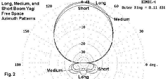
| Fig. 2 provides an overlay of the
28.5 MHz free space azimuth patterns of all three antenna
designs. We may note the forward gain peaks, which just
about correlate to the differentials in boom length. The
rear lobes give us much more valuable information. Here
we see that the long-boom design has three small lobes of
roughly equal size so that the front-to-back ratio in the
table gives a fair appraisal of the overall front-to-rear
performance. In contrast, the other two models have
deeper 180-degree "dimples," combined with much
stronger angling lobes. When averaged out, none of the
antennas has much of an advantage over the other. Indeed,
anything above 20-dB front-to-back ratio overall might be
considered outstanding. To this point, it may seem that the decision we need to make is one of gain advantage vs. mechanical disadvantage to a longer boom. However, let us not be so swift to judgment. For I have once more misled you by giving you the peak or nearly peak performance of the antenna at one frequency. The next question is how each of these designs performs across an entire ham band. Since the first MHz of 10 meters is the greatest stretch for these designs (because 20 and 15 are proportionately narrower), let's sweep the antennas across the 28 to 29 MHz range and see how the performance of each holds up. |
|
|
| In Fig. 3, we have the gain of the three designs across the pass band. Note that the gain figures in the tables are intermediate values. The gain across the band can vary by as much as 0.4 dB in at least one of the designs. In selecting a design, we must also ask whether the lowest gain--which occurs at the low end of the band for 3-element Yagi designs--is an acceptable figure (when weighed against all of the other factors involved in our decision to build). |
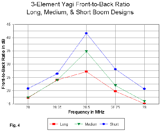 |
| Fig. 4 records the 180-degree front-to-back ratios across the pass band. Here we can either be impressed by the peak values, or we can take a closer look at the values at the band edges. The short-boom design actually excels in this department, with no value falling below 20 dB. The other two designs are remarkably close in their band edge values, which are about 17 dB at the low end and 15-16 dB at the high end. Before settling on a design for the two lower bands, we should remember that these bands are only 68% to 70% as wide as the 10-meter passband. Hence, we can achieve better band-edge results by centering the peaks in our final design. |
 |
| A rough measure of whether we shall
be able to effect a wide-band match to a 50-Ohm cable can
be derived from the SWR curve of the antenna related to
the resonant impedance before matching. Since the
feedpoint impedance of all three models is so close to 25
Ohms, we can use that number as representative of the
resonant feedpoint impedance. Then we can evaluate the
SWR curves in Fig. 5. For all three designs, the SWR climb more quickly above the resonant design frequency than below it. On 10 meters, this means exceeding a 2:1 SWR value at the upper end of the pass band for two of the three designs. However, all three designs will likely show under 2:1 SWR across the narrower reaches of 20 and 15 meters. The short boom design shows the flattest curve. Although the designs were set up for a resonant feedpoint impedance (little or no reactance), one can extend or shrink the driver length as necessary to use any of the common matching system: beta, gamma, Tee. Of course, a 1/4 wl section of 35-37 Ohm coax will provide a matching section to a 50-Ohm main line if we leave the feedpoints resonant. We shall look in more detail at typical matching systems before we are done. So it looks like we are almost ready to make a decision. Seemingly, all we need to do is to look at how the elements might change if we use several diameters of tubing for each one. Not so fast. We have not yet looked at truly wide-band designs to see if they hold any advantages and what those advantages might be. So while we are still in this preliminary stage of design evaluation, let's look next month at a pair of wide-band Yagi designs.
|
Director/Driven
Element 2-Element Yagis
|
|
| Figure
1 shows the construction of a reasonable D/DE Yagi. The
1" elements of this 10-meter model are feasible
hardware store material, but the model is designed less
to build than to set the properties of the genre of beam.
With wider spacing, the antenna gain drops off, although
the feedpoint impedance goes up. Closer spacing raises
gain for a while, but continuously drops the feedpoint
impedance. The model antenna, set for 28.5 MHz, has a
feedpoint impedance of 20.5 - j23.5 ohms, just about
right for a hairpin or inductor beta match of very
conventional design. Incidentally, HAMCALC has a very nice program for calculating beta matches, including the hairpin. The equivalent inductance is also given, which permits you to use another program on HAMCALC to create a coil instead. See the basic "Radio" page for the address of VE3ERP, the master of this suite of GW BASIC utility programs. With only slight readjustments, the basic 2-element D/DE Yagi can be swept through a variety of radiation patterns. Three of them are illustrated in Figure 2. The Maximum Front-to-Back settings will yield a modest gain (about 6.5 dBi free space) and a very good (greater than 20 dB) front-to-back ratio with a feedpoint impedance of about 20 ohms. At the other extreme, maximum gain provides over 7 dBi gain but under 10 dB front-to-back and a feedpoint impedance of about 10 ohms. There is a midpoint setting shown in the patterns, where the gain is intermediate, the front-to-back is respectable, and the feedpoint Z is about 15 ohms. |
 |
| These
setting are not so very far apart, and a frequency
difference of about 1.5% will sweep you through them. A
little further, and you will experience pattern reversal.
On 10 meters, this is under 400 kHz. So unless your needs
are very frequency specific, the D/DE Yagi may not be a
good design choice. However, on the WARC bands, no such problems occur. On 12 and 17 meters, the available bandwidth is about 1/2 of 1% of the frequency, and the D/DE design can easily cover this spread with stable characteristics. Back-to-Back 12-17-Meter YagisOne of the chief attractions of the D/DE design is the short boom length required for the antenna. For example, 0.07 wl is only 3.8' at 17 meters (with elements between 26 and 28') and 2.75' at 12 meters (with elements between 18 and 20'). Modeling suggests that individual antennas for these two bands show very little interaction when placed back-to-back and separated by about a foot or more. Hence, an 8' boom would hold back-to- back individual antennas. Individual antennas, however, require separate feedlines or a switching system. We can make life even simpler and cut the feedline needs down to 1 feedline. By placing the driven elements close together, we can use open-sleeve coupling. This involves connecting the feedline permanently to the 17 meter driven element and letting it excite the 12 meter element when fed with 12 meter energy. The required spacing is just about 4" which requires that we retune the 12 meter elements for this configuration. Once done, however, the two beams do their jobs with few signs of other interactions. Moreover, the two antennas require only a 7' boom. To test this idea, I created models of a double D/DE Yagi using open sleeve coupling and placed back-to-back. I used an aggressive stepped diameter tubing schedule to keep the antenna array as light as possible. Figure 3 shows a sketch of the overall dimensions of the antenna. |
 |
Since the tubing
schedule would not show well in the sketch, here is the
antenna description file with a detailed list of lengths
and diameters of aluminum tubing. --------------- WIRES --------------- Wire Conn.--- End 1 (x,y,z : ft) Conn. -- End 2 (x,y,z : ft) Dia(in) 12-meter director 1 -9.570, 3.080, 0.000 W2E1 -6.500, 3.080, 0.000 3.75E-01 2 W1E2 -6.500, 3.080, 0.000 W3E1 -2.500, 3.080, 0.000 5.00E-01 3 W2E2 -2.500, 3.080, 0.000 W4E1 -1.000, 3.080, 0.000 6.25E-01 4 W3E2 -1.000, 3.080, 0.000 W5E1 1.000, 3.080, 0.000 7.50E-01 5 W4E2 1.000, 3.080, 0.000 W6E1 2.500, 3.080, 0.000 6.25E-01 6 W5E2 2.500, 3.080, 0.000 W7E1 6.500, 3.080, 0.000 5.00E-01 7 W6E2 6.500, 3.080, 0.000 9.570, 3.080, 0.000 3.75E-01 12-meter driven element 8 -10.120, 0.330, 0.000 W9E1 -6.500, 0.330, 0.000 3.75E-01 9 W8E2 -6.500, 0.330, 0.000 W10E1 -2.500, 0.330, 0.000 5.00E-01 10 W9E2 -2.500, 0.330, 0.000 W11E1 -1.000, 0.330, 0.000 6.25E-01 11 W10E2 -1.000, 0.330, 0.000 W12E1 1.000, 0.330, 0.000 7.50E-01 12 W11E2 1.000, 0.330, 0.000 W13E1 2.500, 0.330, 0.000 6.25E-01 13 W12E2 2.500, 0.330, 0.000 W14E1 6.500, 0.330, 0.000 5.00E-01 14 W13E2 6.500, 0.330, 0.000 10.120, 0.330, 0.000 3.75E-01 17-meter director 15 -13.000, -3.785, 0.000 W16E1 -9.000, -3.785, 0.000 5.00E-01 16 W15E2 -9.000, -3.785, 0.000 W17E1 -3.500, -3.785, 0.000 6.25E-01 17 W16E2 -3.500, -3.785, 0.000 W18E1 -1.500, -3.785, 0.000 7.50E-01 18 W17E2 -1.500, -3.785, 0.000 W19E1 1.500, -3.785, 0.000 8.75E-01 19 W18E2 1.500, -3.785, 0.000 W20E1 3.500, -3.785, 0.000 7.50E-01 20 W19E2 3.500, -3.785, 0.000 W21E1 9.000, -3.785, 0.000 6.25E-01 21 W20E2 9.000, -3.785, 0.000 13.000, -3.785, 0.000 5.00E-01 17-meter driven element 22 -13.850, 0.000, 0.000 W23E1 -9.000, 0.000, 0.000 5.00E-01 23 W22E2 -9.000, 0.000, 0.000 W24E1 -3.500, 0.000, 0.000 6.25E-01 24 W23E2 -3.500, 0.000, 0.000 W25E1 -1.500, 0.000, 0.000 7.50E-01 25 W24E2 -1.500, 0.000, 0.000 W26E1 1.500, 0.000, 0.000 8.75E-01 26 W25E2 1.500, 0.000, 0.000 W27E1 3.500, 0.000, 0.000 7.50E-01 27 W26E2 3.500, 0.000, 0.000 W28E1 9.000, 0.000, 0.000 6.25E-01 28 W27E2 9.000, 0.000, 0.000 13.850, 0.000, 0.000 5.00E-01 The feedpoint is on wire #25, the center of the 17-meter driven element. Do not expect the model to be exact on the spacing for the open sleeve coupling distance. Rather, experiment and measure the impedance on both bands as you work. The center of gravity should be just on the 17-meter side of the 17-meter driven element, minimizing the need for coax to run along the boom. Almost any boom in the 1.25" range should do, even a length of the lighter TV masting (which is too light for mast use), as long as it is weather protected so that it does not rust out in a year. Even hardware store aluminum with a wall thickness of 0.055" should handle the job, although inserts at the element clamping points should be used to prevent tube crush. Alternatively, you can use short sections of the next tubing size up as strengtheners at the element clamping points. The model is designed for elements insulated from the boom, so if you use direct clamping to the boom, expect to adjust element lengths a bit. The feedpoint impedance is just about 21 ohms resonant for both frequency ranges. This permits the use of a broad-band balun to feed the antenna and effect an impedance transformation to the 50-ohm coax line. alternatively, the antenna lengths can be reset to show capacitive reactance. A Beta match usually is effective not only at the frequency for which it is designed, but as well at higher frequencies, and with a little juggling of dimensions, a 2-band match should be obtained. |
 |
| Figure 4 shows the
patterns of the two antennas in one back-to-back pattern
at free space. At 70' up, the gain is in the neighborhood
of 12 dBi, a little under 5 dB better than a dipole, and
with a strong front-to-back ratio. The back-to-back open-sleeve D/DE Yagis are not world beaters, but they are a. inexpensive to build, and b. lots better than some of the antennas being pressed into service for these bands. The entire antenna, boom and all, should weight in at less than 20 pounds, making it a good candidate for stacking on top of an existing antenna. If you separate the two antennas, you will have to adjust the dimensions--especially of the 12-meter model--for independent use. Likewise, if you use different materials or a different schedule of diameter steps, you will also have to adjust the dimensions to restore the pattern and the feedpoint impedance. But that comes with the territory of antenna experimenting and home-brewing. 12-17-Meter 2-Element Yagis Facing the Same WayIs it feasible to place the two antennas in the same plane using the open-sleeve coupling system for a single feed line? The answer is yes and no. Yes, it is possible to develop a set of dimensions that will produce good performance at a desirable feed impedance for one frequency within the upper band. (The lower band is not affected.) However, both elements for the upper band are inside the elements for the lower band, producing a "cage" effect. The chief problem created is an extreme narrow bandwidth for desireable characteristics. In terms of this design, when the beams face in opposite directions, they show an operating bandwidth for under 2:1 SWR in excess of the 100 kHz width of the bands. When caged (or facing in the same direction), the operating bandwidth of the upper band beam is far less than the width of the band. For building and tuning, this also means that hitting the precisely needed dimensions is very tricky--and the settings are very susceptible to the need for change with changes of antenna height below about 1.5 wl. Hence, my recommendation is for opposing directions or for combinations of beam types, where the upper band antenna is "uncaged." (Yes, I know, I watch too many wildlife documentaries and it is affecting my choice of terminology.) There is an alternative that achieves the uncaging. It has the disadvantages, relative to the Janus-faced design above, of requiring a longer boom (10') and sacrificing a good bit of 17-meter front-to-back ratio. On the other hand, the beams face the same direction and require a single directly-matched 50-Ohm feed to cover both bands. The design is a DE-Reflector for 17 and a DE-Director for 12. By keeping the elements for each band together, they remain uncaged. In addition, there is a slight forward stagger effect so that the beams have marginally higher values than when they are independent. With the spacing used, the feedpoint impedance on both bands is close to 50 Ohms. The outline dimensions are shown in Figure 5. |
|
| The same
caution about spacing of the open-sleeve coupled driven
elements applies to both designs: the builder will have
to adjust both length and spacing of the 12-meter slaved
driver, since the modeling program is close to its limits
for handling closely spaced elements of different
lengths. However, the model should be quite close. In addition, the antenna was designed with a tapering schedule in place. Here is the detailed wire table. --------------- WIRES --------------- Wire Conn. --- End 1 (x,y,z : ft) Conn. --- End 2 (x,y,z : ft) Dia(in) Segs 12-meter Director 1 -9.500, 3.130, 0.000 W2E1 -6.500, 3.130, 0.000 3.75E-01 5 2 W1E2 -6.500, 3.130, 0.000 W3E1 -2.500, 3.130, 0.000 5.00E-01 5 3 W2E2 -2.500, 3.130, 0.000 W4E1 -1.000, 3.130, 0.000 6.25E-01 2 4 W3E2 -1.000, 3.130, 0.000 W5E1 1.000, 3.130, 0.000 7.50E-01 3 5 W4E2 1.000, 3.130, 0.000 W6E1 2.500, 3.130, 0.000 6.25E-01 2 6 W5E2 2.500, 3.130, 0.000 W7E1 6.500, 3.130, 0.000 5.00E-01 5 7 W6E2 6.500, 3.130, 0.000 9.500, 3.130, 0.000 3.75E-01 5 12-meter Driver 8 -10.070, 0.380, 0.000 W9E1 -6.500, 0.380, 0.000 3.75E-01 5 9 W8E2 -6.500, 0.380, 0.000 W10E1 -2.500, 0.380, 0.000 5.00E-01 5 10 W9E2 -2.500, 0.380, 0.000 W11E1 -1.000, 0.380, 0.000 6.25E-01 2 11 W10E2 -1.000, 0.380, 0.000 W12E1 1.000, 0.380, 0.000 7.50E-01 3 12 W11E2 1.000, 0.380, 0.000 W13E1 2.500, 0.380, 0.000 6.25E-01 2 13 W12E2 2.500, 0.380, 0.000 W14E1 6.500, 0.380, 0.000 5.00E-01 5 14 W13E2 6.500, 0.380, 0.000 10.070, 0.380, 0.000 3.75E-01 5 17-meter Driver 15 -13.100, 0.000, 0.000 W16E1 -9.500, 0.000, 0.000 3.75E-01 4 16 W15E2 -9.500, 0.000, 0.000 W17E1 -6.750, 0.000, 0.000 5.00E-01 4 17 W16E2 -6.750, 0.000, 0.000 W18E1 -4.000, 0.000, 0.000 6.25E-01 4 18 W17E2 -4.000, 0.000, 0.000 W19E1 4.000, 0.000, 0.000 7.50E-01 11 19 W18E2 4.000, 0.000, 0.000 W20E1 6.750, 0.000, 0.000 6.25E-01 4 20 W19E2 6.750, 0.000, 0.000 W21E1 9.500, 0.000, 0.000 5.00E-01 4 21 W20E2 9.500, 0.000, 0.000 13.100, 0.000, 0.000 3.75E-01 4 17-meter Reflector 22 -14.100, -6.800, 0.000 W23E1 -9.500, -6.800, 0.000 3.75E-01 4 23 W22E2 -9.500, -6.800, 0.000 W24E1 -6.750, -6.800, 0.000 5.00E-01 4 24 W23E2 -6.750, -6.800, 0.000 W25E1 -4.000, -6.800, 0.000 6.25E-01 4 25 W24E2 -4.000, -6.800, 0.000 W26E1 4.000, -6.800, 0.000 7.50E-01 11 26 W25E2 4.000, -6.800, 0.000 W27E1 6.750, -6.800, 0.000 6.25E-01 4 27 W26E2 6.750, -6.800, 0.000 W28E1 9.500, -6.800, 0.000 5.00E-01 4 28 W27E2 9.500, -6.800, 0.000 14.100, -6.800, 0.000 3.75E-01 4 As always, since the taper schedule affects performance, you will have to adjust dimensions to suit the materials you have on hand. Four light-weight elements on a 10' boom should not stress an extended mast used to stack this simple beam above a heavy-weight tribander. As Figure 6 shows, the gain of the two beams is about the same--between 6.3 and 6.4 dBi in free space. However, the 17-meter front-to-back ratio is reduced considerably. However, until the WARC bands become seriously over-crowded, this may not be a major problem. |
 |
Back-to-Back with a 30-Meter Dipole BetweenA couple of requests came in for an odd combo: a 30-m dipole wit the back to back 17-12 Yagi combo. This combo would fit on an 8' boom, with the big dipole (48.6') centered at the mast--but perhaps due to the greater weight of the 17-meter Yagi and the longer boom to that side, offset so that the dipole did not sit right on the mast. Such an antenna is possible, and the sketch shows its outline (Figure 7) |
 |
| The dipole is now the
fed element, with both Yagi drivers open-sleeve coupled.
The frequency ratio for the 17-meter driver
(10.125:18.118) is low enough to make it easy to preserve
the full performance of the 2-element DE-Dir beam (6.5
dBi/28 dB F-B) with a 53-Ohm feedpoint impedance. The
frequency ratio for the 12-meter driver (10.125:24.95) is
large enough to adversely affect performance to a small
degree (6.3 dBi/20 dB F-B) with a 47-Ohm feedpoint
impedance. The dipole pattern is slightly flattened as
the Yagis stretch it in the planar directions--the amount
is about 0.2 dB. The dipole impedance in free space
showed about 78 Ohms. In all cases, the impedance figures
are good enough for standard coax feed systems. Here is the modeled wire table for the 3-band antenna. Unfortunately, I lack ftp capabilities and cannot provide a downloadable .NEC or .EZ file. --------------- WIRES --------------- Wire Conn. --- End 1 (x,y,z : ft) Conn. --- End 2 (x,y,z : ft) Dia(in) Segs 12-m director 1 -9.600, 3.340, 0.000 W2E1 -6.500, 3.340, 0.000 3.75E-01 5 2 W1E2 -6.500, 3.340, 0.000 W3E1 -2.500, 3.340, 0.000 5.00E-01 5 3 W2E2 -2.500, 3.340, 0.000 W4E1 -1.000, 3.340, 0.000 6.25E-01 2 4 W3E2 -1.000, 3.340, 0.000 W5E1 1.000, 3.340, 0.000 7.50E-01 3 5 W4E2 1.000, 3.340, 0.000 W6E1 2.500, 3.340, 0.000 6.25E-01 2 6 W5E2 2.500, 3.340, 0.000 W7E1 6.500, 3.340, 0.000 5.00E-01 5 7 W6E2 6.500, 3.340, 0.000 9.600, 3.340, 0.000 3.75E-01 5 12-m driver 8 -10.050, 0.600, 0.000 W9E1 -6.500, 0.600, 0.000 3.75E-01 5 9 W8E2 -6.500, 0.600, 0.000 W10E1 -2.500, 0.600, 0.000 5.00E-01 5 10 W9E2 -2.500, 0.600, 0.000 W11E1 -1.000, 0.600, 0.000 6.25E-01 2 11 W10E2 -1.000, 0.600, 0.000 W12E1 1.000, 0.600, 0.000 7.50E-01 3 12 W11E2 1.000, 0.600, 0.000 W13E1 2.500, 0.600, 0.000 6.25E-01 2 13 W12E2 2.500, 0.600, 0.000 W14E1 6.500, 0.600, 0.000 5.00E-01 5 14 W13E2 6.500, 0.600, 0.000 10.050, 0.600, 0.000 3.75E-01 5 17-m driver 15 -13.780, -0.620, 0.000 W16E1 -9.000, -0.620, 0.000 5.00E-01 6 16 W15E2 -9.000, -0.620, 0.000 W17E1 -3.500, -0.620, 0.000 6.25E-01 6 17 W16E2 -3.500, -0.620, 0.000 W18E1 -1.500, -0.620, 0.000 7.50E-01 3 18 W17E2 -1.500, -0.620, 0.000 W19E1 1.500, -0.620, 0.000 8.75E-01 5 19 W18E2 1.500, -0.620, 0.000 W20E1 3.500, -0.620, 0.000 7.50E-01 3 20 W19E2 3.500, -0.620, 0.000 W21E1 9.000, -0.620, 0.000 6.25E-01 6 21 W20E2 9.000, -0.620, 0.000 13.780, -0.620, 0.000 5.00E-01 6 17-m director 22 -13.050, -4.480, 0.000 W23E1 -9.000, -4.480, 0.000 5.00E-01 6 23 W22E2 -9.000, -4.480, 0.000 W24E1 -3.500, -4.480, 0.000 6.25E-01 6 24 W23E2 -3.500, -4.480, 0.000 W25E1 -1.500, -4.480, 0.000 7.50E-01 3 25 W24E2 -1.500, -4.480, 0.000 W26E1 1.500, -4.480, 0.000 8.75E-01 5 26 W25E2 1.500, -4.480, 0.000 W27E1 3.500, -4.480, 0.000 7.50E-01 3 27 W26E2 3.500, -4.480, 0.000 W28E1 9.000, -4.480, 0.000 6.25E-01 6 28 W27E2 9.000, -4.480, 0.000 13.050, -4.480, 0.000 5.00E-01 6 30-m dipole 29 -24.300, 0.000, 0.000 W30E1 -17.500, 0.000, 0.000 5.00E-01 5 30 W29E2 -17.500, 0.000, 0.000 W31E1 -12.650, 0.000, 0.000 6.25E-01 5 31 W30E2 -12.650, 0.000, 0.000 W32E1 -7.150, 0.000, 0.000 7.50E-01 5 32 W31E2 -7.150, 0.000, 0.000 W33E1 -5.150, 0.000, 0.000 8.75E-01 2 33 W32E2 -5.150, 0.000, 0.000 W34E1 -2.000, 0.000, 0.000 1.00E+00 3 34 W33E2 -2.000, 0.000, 0.000 W35E1 2.000, 0.000, 0.000 1.12E+00 3 35 W34E2 2.000, 0.000, 0.000 W36E1 5.150, 0.000, 0.000 1.00E+00 3 36 W35E2 5.150, 0.000, 0.000 W37E1 7.150, 0.000, 0.000 8.75E-01 2 37 W36E2 7.150, 0.000, 0.000 W38E1 12.650, 0.000, 0.000 7.50E-01 5 38 W37E2 12.650, 0.000, 0.000 W39E1 17.500, 0.000, 0.000 6.25E-01 5 39 W38E2 17.500, 0.000, 0.000 24.300, 0.000, 0.000 5.00E-01 5 As with the other designs, you will have to experiment for other taper schedules to the elements. Likewise, the exact lengths and spacing of the drivers from the dipole will also be am tter of experimentation. If you shorten the dipole by any other means than a capacity hat on each end, the performance of the Yagis will be thrown off due to the altered current levels along parts of the dipole providing the drive for the coupled Yagi drivers. Even mid-element loads throw everything off. Capacity hats do preserve the current levels along the shortened dipole at the same magnitude as with a full size dipole; however, the hats will necessarily by large enough to possible couple to the Yagi driver ends. No doubt further modeling time could yield improved performance from the 12-m Yagi, with many iterations of element length, spacing, and spacing from the dipole changes. But the figures shown here sould suffice as a starting point for individual experimentation. A Forward-Facing 17-12 Combo with Higher Gain on 12It is possible to obtain greater gain on 12 meters with a forward-facing combination of a Driver-Reflector Yagi for 17 and a driver-director Yagi for 12, using the same forward-stagger and open-sleeve principles of the earlier 4-element (2 per band) we looked at earlier. The way to more gain is to add another director for 12 meters. The general outline looks like Figure 8. |
|
| If we compare this
5-element Yagi to the forward-facing 4-element version
earlier, we shall see several differences. First, the
reflector spacing has been increased. The chief result of
this move is to increase the resistive component of the
feedpoint impedance. The essential performance on 17 is
not changed. You can feel free to use any spacing from
the close spacing of the 4-element version to the wide
spacing of this version. Second, adding a second director changes the director dimensions and lengthens the boom considerable--a total of 17' for the entire array. However, besides obtaining better gain on 12, the array is less sensitive to minor changes of length of the 2 directors. What you might change slightly by a small alteration of one element's length can be restored by slightly altering the length of the other director. The NEC-4 modeled performance of this array is given in the following table: Freq Gain FS F-B R +/- jX SWR 18.068 6.30 11.89 62.1 - j 4.7 1.26 18.118 6.25 11.92 64.2 - j 3.1 1.29 18.168 6.20 11.91 66.3 - j 1.6 1.32 24.89 7.16 13.75 57.1 + j 6.9 1.20 24.94 7.21 13.82 54.9 + j 8.9 1.22 24.95 7.26 13.87 52.8 + j11.1 1.25 It is possible to optimize this design further. The 17-meter section can be set closer to 50 Ohms, although significant increases in gain and front-to-back ratio are not possible with only 2 elements. The gain and front-to-back ratio on 12 can also be altered, but improving one results in decreases to the other. This version has opted for gain and only a modest front-to-back ratio. Comparative patterns for the 2 bands appear in Figure 9. |
 |
As always, models of
open sleeve coupling are approximate only. Therefore,
expect to play a bit with the length of the 12-meter
slaved driver and its spacing from the 17-meter fed
driver to achieve the desired 12-meter feedpoint
impedance. Such adjustments have little or no effect on
the 17-meter feedpoint impedance or other operating
parameters on that band. Also, if you select a different
tapering schedule for your elements, do two things. 1.
Check out the potential durability of the element, using
a program like YagiStress or use a model of element taper
that has a proven record. 2. Adjust the element lengths
to suit the Leeson corrected substitute uniform diameter
elements that are equivalent to the ones shown here. This
latter task can be handled with one of the antenna
modeling programs. The details of the model on which this
note is based appear in the following EZNEC antenna
description. --------------- WIRES --------------- Wire Conn. --- End 1 (x,y,z : ft) Conn. --- End 2 (x,y,z : ft) Dia(in) Segs 17-Meter Reflector 1 -14.100, 0.000, 0.000 W2E1 -12.250, 0.000, 0.000 5.00E-01 2 2 W1E2 -12.250, 0.000, 0.000 W3E1 -9.500, 0.000, 0.000 6.25E-01 3 3 W2E2 -9.500, 0.000, 0.000 W4E1 -6.750, 0.000, 0.000 7.50E-01 3 4 W3E2 -6.750, 0.000, 0.000 W5E1 -4.000, 0.000, 0.000 8.75E-01 3 5 W4E2 -4.000, 0.000, 0.000 W6E1 4.000, 0.000, 0.000 1.00E+00 9 6 W5E2 4.000, 0.000, 0.000 W7E1 6.750, 0.000, 0.000 8.75E-01 3 7 W6E2 6.750, 0.000, 0.000 W8E1 9.500, 0.000, 0.000 7.50E-01 3 8 W7E2 9.500, 0.000, 0.000 W9E1 12.250, 0.000, 0.000 6.25E-01 3 9 W8E2 12.250, 0.000, 0.000 14.100, 0.000, 0.000 5.00E-01 2 17-Meter Fed Driver 10 -13.167, 9.158, 0.000 W11E1 -11.250, 9.158, 0.000 5.00E-01 2 11 W10E2 -11.250, 9.158, 0.000 W12E1 -8.500, 9.158, 0.000 6.25E-01 3 12 W11E2 -8.500, 9.158, 0.000 W13E1 -5.750, 9.158, 0.000 7.50E-01 3 13 W12E2 -5.750, 9.158, 0.000 W14E1 -4.000, 9.158, 0.000 8.75E-01 3 14 W13E2 -4.000, 9.158, 0.000 W15E1 4.000, 9.158, 0.000 1.00E+00 9 15 W14E2 4.000, 9.158, 0.000 W16E1 5.750, 9.158, 0.000 8.75E-01 3 16 W15E2 5.750, 9.158, 0.000 W17E1 8.500, 9.158, 0.000 7.50E-01 3 17 W16E2 8.500, 9.158, 0.000 W18E1 11.250, 9.158, 0.000 6.25E-01 3 18 W17E2 11.250, 9.158, 0.000 13.167, 9.158, 0.000 5.00E-01 2 12-meter "Slave" Driver 19 -9.833, 9.575, 0.000 W20E1 -6.250, 9.575, 0.000 3.75E-01 4 20 W19E2 -6.250, 9.575, 0.000 W21E1 -2.500, 9.575, 0.000 5.00E-01 4 21 W20E2 -2.500, 9.575, 0.000 W22E1 -0.500, 9.575, 0.000 6.25E-01 3 22 W21E2 -0.500, 9.575, 0.000 W23E1 0.500, 9.575, 0.000 7.50E-01 1 23 W22E2 0.500, 9.575, 0.000 W24E1 2.500, 9.575, 0.000 6.25E-01 3 24 W23E2 2.500, 9.575, 0.000 W25E1 6.250, 9.575, 0.000 5.00E-01 4 25 W24E2 6.250, 9.575, 0.000 9.833, 9.575, 0.000 3.75E-01 4 12-Meter Director 1 26 -9.500, 10.683, 0.000 W27E1 -6.250, 10.683, 0.000 3.75E-01 4 27 W26E2 -6.250, 10.683, 0.000 W28E1 -2.500, 10.683, 0.000 5.00E-01 4 28 W27E2 -2.500, 10.683, 0.000 W29E1 -0.500, 10.683, 0.000 6.25E-01 3 29 W28E2 -0.500, 10.683, 0.000 W30E1 0.500, 10.683, 0.000 7.50E-01 1 30 W29E2 0.500, 10.683, 0.000 W31E1 2.500, 10.683, 0.000 6.25E-01 3 31 W30E2 2.500, 10.683, 0.000 W32E1 6.250, 10.683, 0.000 5.00E-01 4 32 W31E2 6.250, 10.683, 0.000 9.500, 10.683, 0.000 3.75E-01 4 12-Meter Director 2 33 -8.833, 16.967, 0.000 W34E1 -6.250, 16.967, 0.000 3.75E-01 4 34 W33E2 -6.250, 16.967, 0.000 W35E1 -2.500, 16.967, 0.000 5.00E-01 4 35 W34E2 -2.500, 16.967, 0.000 W36E1 -0.500, 16.967, 0.000 6.25E-01 3 36 W35E2 -0.500, 16.967, 0.000 W37E1 0.500, 16.967, 0.000 7.50E-01 1 37 W36E2 0.500, 16.967, 0.000 W38E1 2.500, 16.967, 0.000 6.25E-01 3 38 W37E2 2.500, 16.967, 0.000 W39E1 6.250, 16.967, 0.000 5.00E-01 4 39 W38E2 6.250, 16.967, 0.000 8.833, 16.967, 0.000 3.75E-01 4 The element taper used here is an adaptation of a commercial design for other bands. 6061-T6 tubing or its equivalent is available from numerous sources. This beam is far from optimized to its maximum possible performance. However, it may provide a further alternative for experimentation. Since numerous commercial beams use booms in the vicinity of 18', a design such as this makes a possible conversion project once you spring the the very long boom tri-bander to use on 20-15-10 meters The End Result is This . . .As W5JH reminded me, the D/DE 2-element Yagi has a natural home on the WARC bands, especially 12 and 17. Matching is straight forward, and performance will be stable across these narrow bands. 0.07 to 0.09 wl makes a good element spacing for a 20-ohm feedpoint impedance, an easy beta match. Combining DE-Dir and DE-Ref designs is certainly feasible and can effect simplicities of matching and use. Combining back-to-back Yagis with a 30-meter dipole is also possible. Whether you go 2-faced or long-boomed, these designs and innumerable possible variations on them should serve many needs on 12 and 17. Moreover, as this little exercise has shown, the possibilities for experimentation are endless. |
|
|
![]()