bench.jpg
351.67 Kb
F-response1.jpg
282.10 Kb
F-response2.jpg
284.35 Kb
inside.jpg
1058.92 Kb
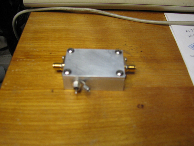
outside1.jpg
297.53 Kb
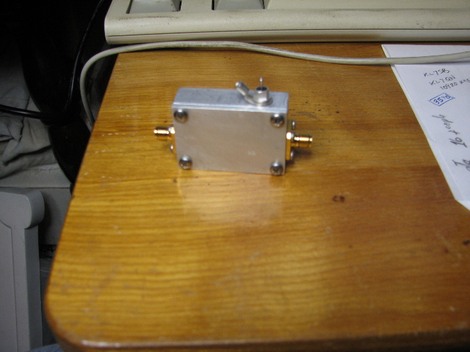
outside2.jpg
307.82 Kb
NF-G.jpg
266.60 Kb
NFmeter.jpg
316.58 Kb
sga4586.gif
41.97 Kb
Evaluation of SGA4586 MMIC Amplifier
|
bench.jpg 351.67 Kb |
F-response1.jpg 282.10 Kb |
F-response2.jpg 284.35 Kb |
|
inside.jpg 1058.92 Kb |
outside1.jpg 297.53 Kb |
outside2.jpg 307.82 Kb |
|
NF-G.jpg 266.60 Kb |
NFmeter.jpg 316.58 Kb |
sga4586.gif 41.97 Kb |
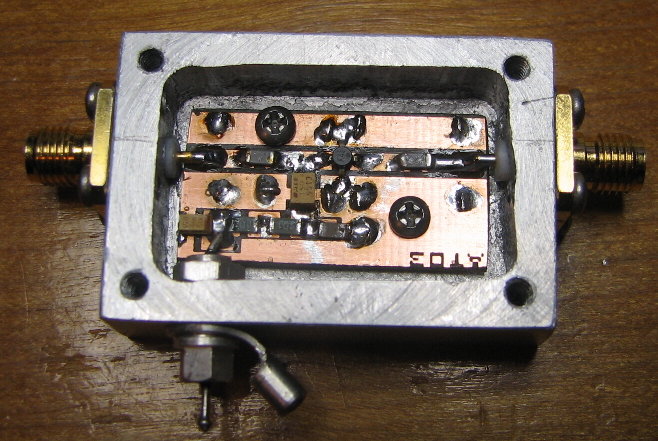
Critique: (in my humble opinion):
1. Printed circuit board - I think the trace width is wrong width for 50 ohms. Did you calculate this for 1/16" fiberglass FR4?
2. It would be best if the inductor did not have the little "T" junction. This looks like a discontinuity of impedance. If the trace is necessary it should be very narrow (high impedance). Otherwise the inductor should just be soldered to the 50 ohm stripline.
3. I believe 12v is the predominant voltage used. So instead of cutting the trace, the option should be to add a jumper.
4. I trimmed the PCB so that there is no ground between the 50 ohm stripline and the edge of the board, for connection to the in/out connector.
5. Space in between some of the traces is VERY small. Should widen a bit.
6. Consideration should be given to mounting. There is little room for mounting screws. It is best to have screws on either side of the 50 ohm stripline especially right at the input.
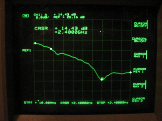
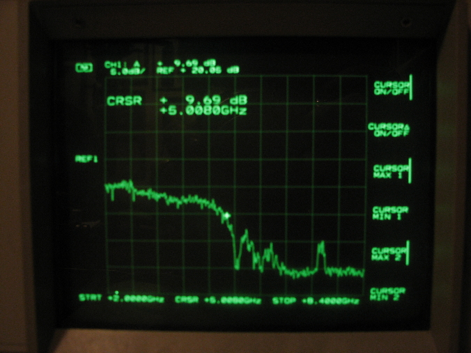
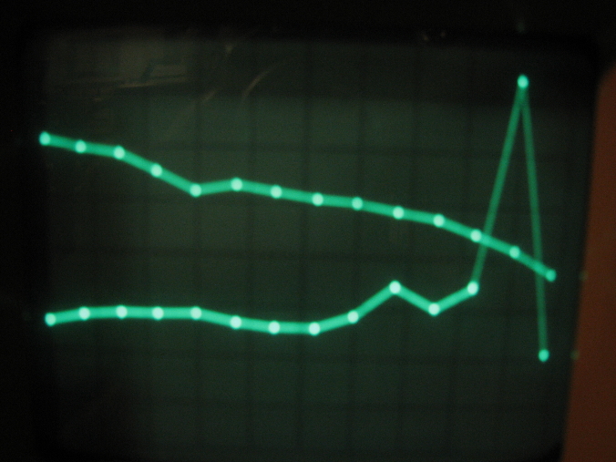
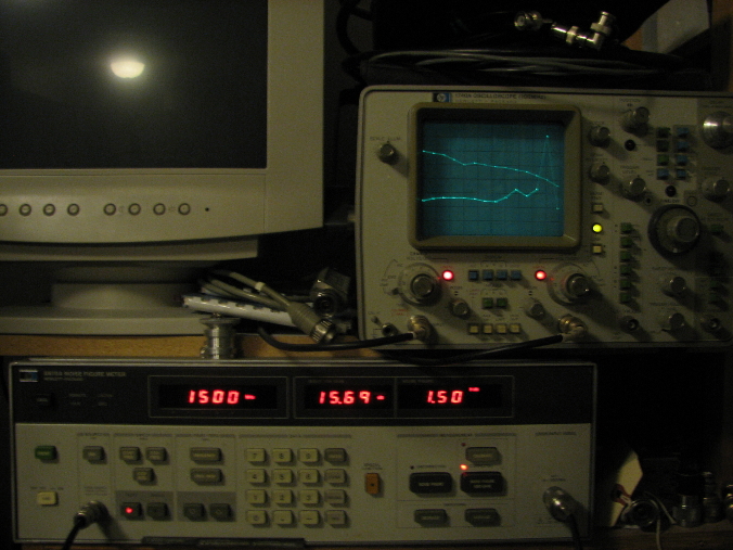
7. In general the overall performance of the amp is very good. I was surprised to see it still amplifying almost 10dB at 5 GHz. I did not measure noise figure above 1.5 GHz. In fact the display shows a spike in NF that I am sure is not actually there. I may try to measure NF at higher frequencies later. I have to set up an external mixer and did not have time for this. I measured input and output return loss. Input RL is less than 5dB across the spectrum. Output RL is greater than 10 dB over most of the spectrum. Also I looked way up in spectrum for any oscillations and there were none.
Thanks......Mike