The KC8RKQ 2 Meter Coathanger Antenna Experiment
Being that I live in a Basement apartment, and the landlord
didn't want me attaching an antenna permanently to the building, I decided
to compromise with this. It works, and I'm able to hit one of the repeaters
in Fenton, Michigan, which is over 30 miles away, on low power (7 watts) using
my ADI AR-146.
When I build my next one, I'll remember to take pictures
along the way so I can show how I constructed it. I'll try to explain it as
best I can below.
Here's three views of the antenna, with descriptions. I apologize
in advance for the poor quality of these. Best I can do with the equipment
I have.

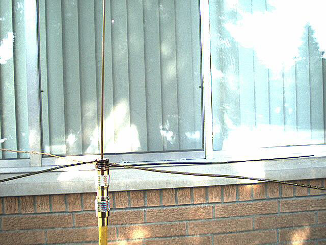
A side view of the antenna. You can see it's zip tied to
the railing around the "fire escape" from the basement apartment. The window
top just barely in view in the bottom center of the picture (by the yellow
coax cable) is one of the windows from my apartment. The ground plane elements
of the antenna are roughly 4 1/2 feet off the ground.
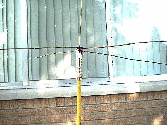
Here we see a close-up of the "mount" for the antenna,
and the coax. It looks like alot more than it needs to be, but I'll explain
why I did it this way below.
This view shows the coax connector unscrewed from the SO-239
butt splice connector.. The antenna can be removed for cleaning, coax replacement,
or whatever. The coax is Thick Ethernet cable, 52 ohm impedance, and double
shielded. It's stiff stuff, and should hold the antenna upright in a modest
wind.
How it was built:
Basically, this antenna cost me $9.19 US to build, and
that included the PL-259's for the coax as well.
First I took a piece of coathanger,
about 21" long, and soldered it into one PL-259 from the coax side. The coathanger
sticks out the coax side of the PL-259 connector.
Next, I screwed the PL-259 into the dual
SO-239 butt splice connector. Basically this is a "barrel" to join two pieces
of coax. I had a different idea for this one. Once the PL-259 was securely
screwed onto the barrel, I went on to the next step.
This was the "fun" part. I got out 4 more
coathangers, and clipped the hanger part off with a pair of cutters, and
straightened them out. I then took one end of each coathanger and bent it
into a loop, so that it would fit snugly over the body of the PL-259. I made
four of these, and staggered them so the two middle ones (from bottom to
top) were 180 degrees opposed, and the top and bottom ones were 180 degrees
opposed.
I then took my butane soldering pencil,
with the "blowtorch" attachment, and heated up the body and the "rings" on
the ground plane elements. I then laid in a healthy amount of solder to make
a good electrical connection, and to hold them in place.
Once this whole assembly cooled down enough,
I measured 20.5 inches from the radiating element, and cut the remaining
coathanger off there.
When I put the antenna up to tune it,
I found I had cut the radiating element too short. A good 2 inches was taken
up inside the PL-259, and I'd forgotten to allow for that. I'm guessing the
radiating element is shielded up until it clears the top (coax end) of the
PL-259, so the system thinks that's part of the coax. I ended up stripping
the "coating" off the top inch or so of the radiating element, and soldering
a 5 inch piece of copper wire onto the end. I stripped about an inch and
a half of insulation off the wire, wrapped it around the top of the coathanger
and just soldered it on, leaving the insulation on the wire. The antenna
was then too long, but still showed a 3:1 match AT WORST on 148.000. I trimmed
the copper wire down until I got the match I wanted, as below.
Freq Match
144.000 1.5:1
146.000 1.2:1
148.000 1.6:1
I could trim it slightly shorter to "even up" the match,
but it's good enough for me right now. When I'm not such a "green" HAM (no
eggs, though), I'll probably work on this design to see if I can't get the
curve flatter, and the match more even.
That's basically the whole story. The antenna works great.
I've got to try some longer distance contacts, to see how far it gets out.
I can hit repeaters in Northville, Howell, Fenton, and South
Lyon on low power (7 watts on my transceiver) without any problems. Maybe
a little bacon frying on the Fenton repeater.
Thanks to:
N8CPO, Ray, for the use of the SWR meter.
KC8HEZ, Rick, for dragging my backsides to the VE's to (finally)
test for my ticket.
WB8HRO, Tim, AA5GO, Greg, and the rest of the members of
the L.A.R.K. for their help, encouragement, and ideas.
73 de KC8RKQ - Chris
P.S. There's More! Click Here!