DDS VFO
|
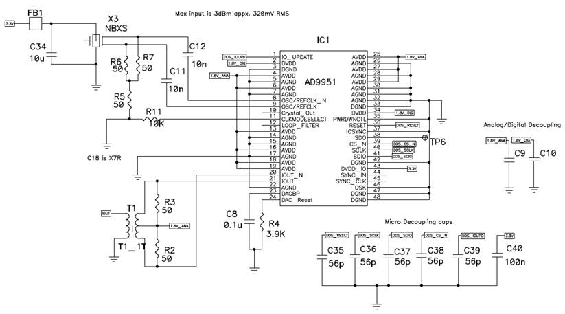
This design is based on the AD9951 DDS
chip – a simple first order phase accumulator. This part has a 14 bit DAC and is used in
the Kenwood TS-590S and other radios.
Reference Clock I am going to use the NBXSBB023 – 400MHz
LVPECL clock oscillator as my reference clock. I have chosen to use a high frequency input
rather than a low frequency that would require the internal clock
multiplier. From the AD9951 data
sheet, it is clear that the lowest phase noise occurs when the internal PLL
clock multiplier is not used. Measurements
of the circuit show that my LVPECL oscillator noise floor is the limiting
factor in the DDS VFO output noise, but it should be ‘good enough’ for ham
radio. Output Transformer I am using the T1-1T+ 50 ohm
transformer. The differential to singled
ended conversion was shown on the AD evaluation board so I decided to use it
as well. From AN-912, the resulting
output voltage will be ~120mV which is not large enough to drive a TUF-1+
mixer which requires a 7dBm drive level. VFO Buffer The MAR-8A+ amplifier has
31.5dB gain. The part can do a maximum
of 12.5dBm, so this is more than adequate to drive my mixer. The series inductor is sized to be 10X
the output impedance (50 ohm) at the lowest operating frequency (30MHz). I will need to adjust the series resistor
for the MAR8 so I can produce 7dBm into a 50 ohm load. +7dBm = 10*log(Pmw)
= 10*log(5mW) = 10*log(mV^2 / 50) Output Elliptic Filter The seventh order elliptic filter was
also shown on the AD evaluation board, but their design has a 200MHz
cutoff. The filter has a sharp
transition from passband to stopband
which will reduce unwanted harmonics.
My design requires a maximum VFO frequency of less than 45MHz so I can
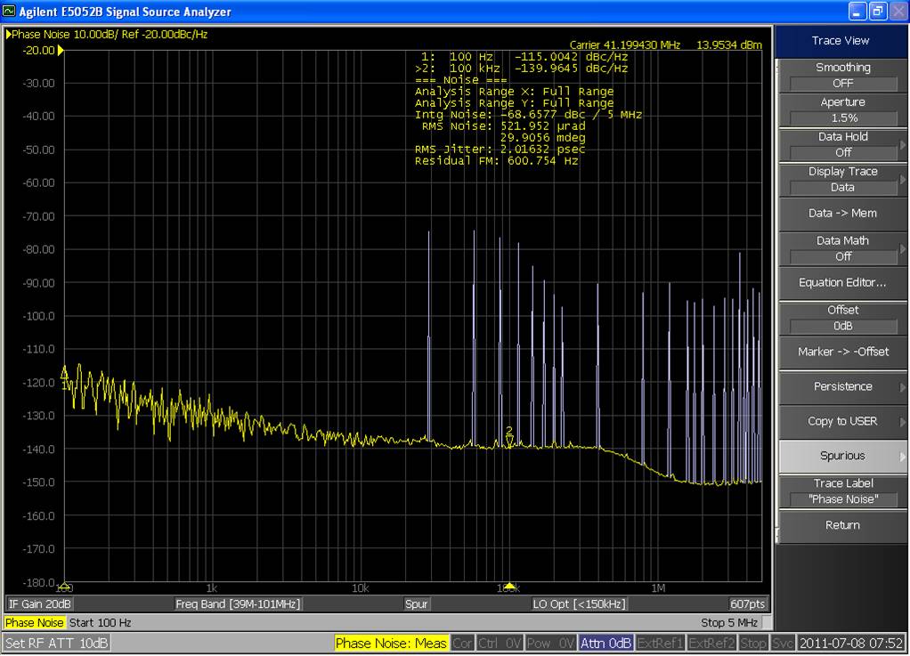
use a lower cutoff frequency than the AD design. Below is a phase noise plot of the
overall DDS performance after the buffer and filter – a whopping 14dBm signal
but I only need 7dBm for my LO so I may back down the drive level.
|