 This
is the front view of my almost completed unit. I used a 3/4 inch angle
aluminum for a frame and have attached the modules to the frame with various
methods. the frame is about 11" X 11" X 10". The small scope I use for
this sits on top.
This
is the front view of my almost completed unit. I used a 3/4 inch angle
aluminum for a frame and have attached the modules to the frame with various
methods. the frame is about 11" X 11" X 10". The small scope I use for
this sits on top.
Last Update 12/17/99
After one year of putting it off building the Hayward/White Spectrum Analyzer featured in QST Aug and Sep 1998 I have finally have some output on the O-scope.
You can buy the kit of boards and parts for about
190 bucks from Kanga US.
Click To Kanga US Web Page
for info
US now has an add-on optional Tracking Generator
for about 40 bucks without mixing xtal (S.A. dependent).
******press thumb nail PIXs below for fullsize PIX. ******
This
is the front view of my almost completed unit. I used a 3/4 inch angle
aluminum for a frame and have attached the modules to the frame with various
methods. the frame is about 11" X 11" X 10". The small scope I use for
this sits on top.
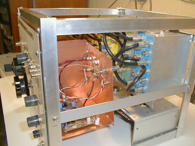 My
SA is using the kit boards and parts but I have scrouged enclosures, cables,
power supply and attenuator to save on cost of project. typical ham actions.
the power supply is at the bottom and to the rear. All the kit boards except
for the Sweep board are housed in small RF tight milled aluminum exclosures
scronged from a dumpster. The sweep board is is a separate PC board HB
enclosure that has sections for the attentuator, xtal calibrator, tracking
Generator interface and all front panel controls.
My
SA is using the kit boards and parts but I have scrouged enclosures, cables,
power supply and attenuator to save on cost of project. typical ham actions.
the power supply is at the bottom and to the rear. All the kit boards except
for the Sweep board are housed in small RF tight milled aluminum exclosures
scronged from a dumpster. The sweep board is is a separate PC board HB
enclosure that has sections for the attentuator, xtal calibrator, tracking
Generator interface and all front panel controls.
 This
is a closer look that the front sweep/attn sections and the lineup of RF
enclosures at the rear. The enclosures already had F-type connectors so
I used them and the cables to match. BTW all unused F-connector milled
and threaded shafts are plugged with as much aluminum foil as possible
to eliminate signal leakage. All DC voltages are entered into these enclosures
via feed-through caps. The power supply is an old linear +/- 15v unit for
another junk source. The attenuator is a high quality 0 - 59 dB unit with
1 dB steps and SMA connectors. The RF input and the Tracking Generator
output interfaces use BNC connectors.
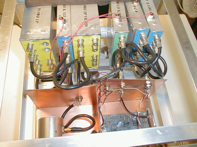
This
is a closer look that the front sweep/attn sections and the lineup of RF
enclosures at the rear. The enclosures already had F-type connectors so
I used them and the cables to match. BTW all unused F-connector milled
and threaded shafts are plugged with as much aluminum foil as possible
to eliminate signal leakage. All DC voltages are entered into these enclosures
via feed-through caps. The power supply is an old linear +/- 15v unit for
another junk source. The attenuator is a high quality 0 - 59 dB unit with
1 dB steps and SMA connectors. The RF input and the Tracking Generator
output interfaces use BNC connectors.
 This
view is from above and back of the unit. the front panel is a double sided
PC board. these front sections will be sealed after complete checkout of
the various modules.
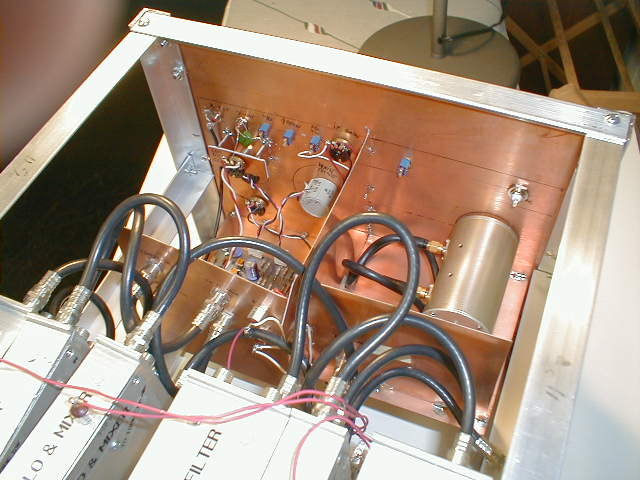
This
view is from above and back of the unit. the front panel is a double sided
PC board. these front sections will be sealed after complete checkout of
the various modules.
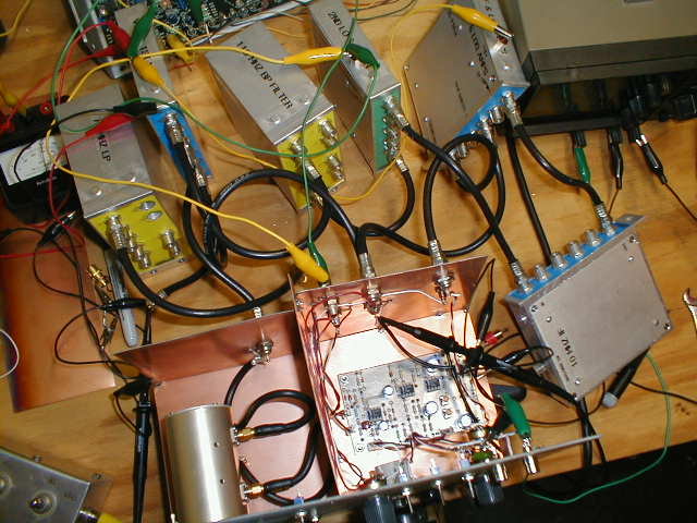 This
is the bench view before the frame was built.
This
is the bench view before the frame was built.
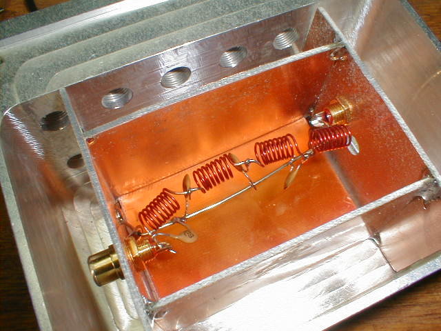 This
is the inter-frame of the 70 mHz Low pass filter. this frame is enclosed
in one of the deeper milled boxes.
This
is the inter-frame of the 70 mHz Low pass filter. this frame is enclosed
in one of the deeper milled boxes.
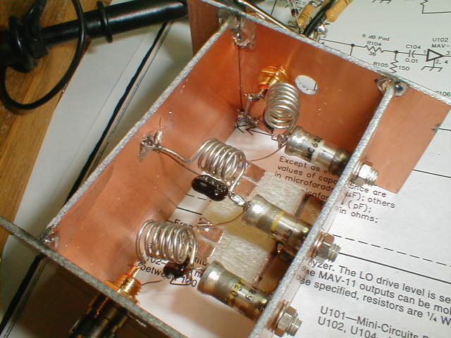 This
is the 110 BandPass filter frame. This early version was modified to have
shields placed between the three sections. I am getting the image
at about -65 dB down from the desired side. This section maybe reworked
at a later date.
This
is the 110 BandPass filter frame. This early version was modified to have
shields placed between the three sections. I am getting the image
at about -65 dB down from the desired side. This section maybe reworked
at a later date.
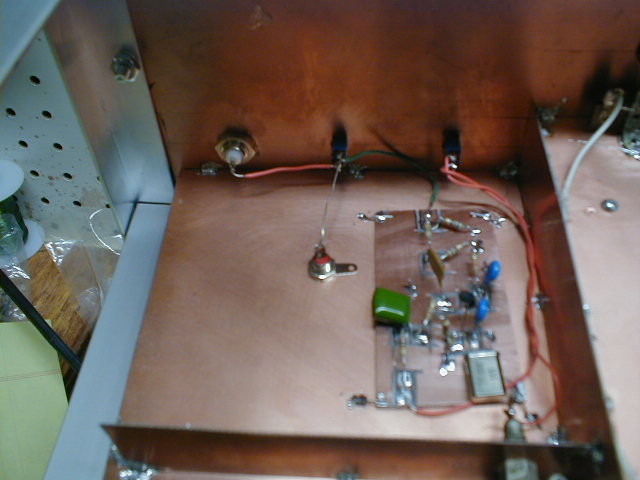 This
is the 10 mHz xtal calibrator board. HB, ugly construction. Power switch
on front panel let you turn it on or off. Source select swtich let's you
pick cal. output vs. external RF source.
This
is the 10 mHz xtal calibrator board. HB, ugly construction. Power switch
on front panel let you turn it on or off. Source select swtich let's you
pick cal. output vs. external RF source.
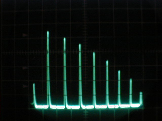 This
is the output from the 10 mHz xtal calibrator in the S.A. The Sweep is
set to max (70 mHz).
This
is the output from the 10 mHz xtal calibrator in the S.A. The Sweep is
set to max (70 mHz).
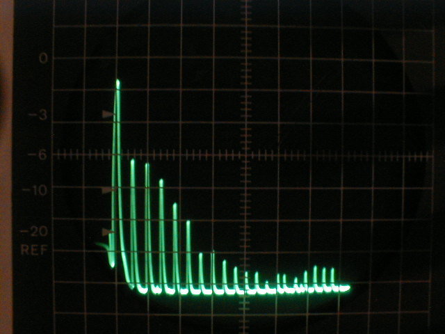 This
is the output from a MightyMite 3.686 mHz QRP transmitter a two transistor
rig @ 50 mW via a 20 dB external attn. This rig is using a three pole PI
LP filter. The unusual baseline at the left of the display is caused by
me overdriving the S.A.
This
is the output from a MightyMite 3.686 mHz QRP transmitter a two transistor
rig @ 50 mW via a 20 dB external attn. This rig is using a three pole PI
LP filter. The unusual baseline at the left of the display is caused by
me overdriving the S.A.
I will be following this up with output PIXs from various tests on gear that I have.
BTW the O-scope is about as basic as you can get.
Sam Billingsley AE4GX Atlanta, GA North Georgia QRP Club