The circuit is the classic detector and two step, meaning detector and two stages of audio.
The coils were wound on old 26 triode tube base ( the filament was open, so I didn't feel too bad about destroying the tube ) with the following turns:
160 m band: 50 turns for the secondary and 15 turns for the tickler, the coils being spaced approx. 1/8 ; freq coverage = 1.43 - 2.66 Mhz
80 m band: 27 turns for the secondary and 8 turns for the tickler, the coils being spaced approx. 1/8 ; freq coverage = 2.1 - 4.5 Mhz
40 m band: 10 turns for the secondary and 3 turns for the tickler, the coils being spaced approx. 1/8 ; freq coverage = 6 - 9 Mhz inch apart.
The tuning ranges are somewhat approximate.
Antenna coupling is through a 1 turn link of #14 house wire concentric with the tuned coil, about 3/4 inch away. This link is in series with a 200 ohm pot, serving as an RF gain control. Tuning was accomplished with a 140 pf bandset capacitor, in parallel with a 15 pf bandspread capacitor, with 15 pf in series to drop the maximum bandspread cap range to about 7.5 pf. I used a national 5:1 velvet vernier for the bandspread dial. Grid leak was 4.7M, and grid cap was 30 pf SM cap. Throttle condensor is a 250 pf air variable.. RF blocking choke is a 2.5 mh. The detector is coupled to the first AF amp with a 6.4H and 1 uf LC combo. This tage is couple to the following stage via 2.2H and 1uf cap. The headphones ( high impedance variety sold by AES ) are in series with the plate and B+ of the final 30 tube. I used those values of chokes only because they were the only ones I had, seemed to work just fine. The plate voltage is about 43 volts, and consists of a string of 9V "transistor" batteries wired in series.
I used a fixed series resistor to drop the voltage from my 3V dry cells to the 2 VDC requirement of the 30's.
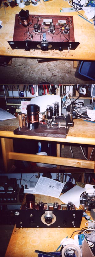
Not shown in the photos above are the two separate power switches I added on the front panel: one for B+ plate, and the other for filament power. I found it useful to turn off B+ during transmit, so I didn't have to listen to the clicking in the headphones.
The circuit was built on some spare particle board I had laying around ( not as aesthetically pleasing as stained pine board ), and used a piece of 1/16 inch steel plate painted flat black .for the front panel. All outside connections to the circuit are made through Pfanestock clips.
Frankly, I was blown away by the performance of this simple receiver, once I got the component values ( esp. tickler winding to tuned coil ratio ) tweaked. There is plenty of volume, regeneration is quite smooth and easy to control, sounds good on CW, SSB, and the SWBC stations.
If you haven't built one of these things, you should make an effort- they are easy to build and fun to operate, and the performance will suprise you. However, plan to do a little bit of experimenting/tweaking of components to get the best results, and don't inadvertently reverse the windings on your tickler coil.
UPDATE!
I have completely revamped this three tube triode regen ( type 30 tubes, detector and two step ). Originally, I started with old tube base coil formers ( 1.25 " dia ) and 26 AWG wire for the tank L, a 33 pf grid cap and 4.7 M grid leak, and 250 pf throttle cap. I had a 140 pf bandset and a 15 pf bandspread cap across the tank. I ditched the tube base plug in coil arrangement that I was using and decided to build a regen strictly for 80 meter CW use, and concentrate on trying to optimize it for the one band. I went for the high L, low C in the tank circuit as recommended by a number of people on the glowbugs email reflector. I used about 35 turns of #18 Awg enamel wire on a 2" diam black PVC pipe former for the secondary winding. This is shunted by a 15 pf air trimmer cap, and a 15 pf main tuning dial cap with a 15 pf SM cap in series with it. So, my total tank C never exceeds about 25 pf ( ignoring stray C ). Used a 10 Meg grid leak and 15 pf mica grid cap. Replaced all the detector wiring with solid #14 AWG house wire. Increased my throttle cap up to 350 pf ( from 250 pf ). I Kept the cap/choke audio coupling arrangement I was using. I ended up with 5 turns for the tickler, spaced about 1/2" from the grid coil winding. I coupled to the antenna via a single turn, 4" diameter loop concentric with the grid coil. The tank coil sits about 7 or 8" back from the front panel, a 1/16" steel plate. 40 VDC on the plates of the tubes. The whole set is built on a piece of cherry-stained poplar.
Here are a few pictures of how the re-vamped regen looks:
Regeneration is extremely smooth ( coming in at about 250 pf) and stable- as smooth or perhaps better than my RAL-7, and the sensitivity was fantastic. Frequency stability and selectivity are very good too.
I'm very pleased with the results, this is my BEST regen yet, and is very suitable for communications purposes.