|
Front panel showing the analog and digital meters. |
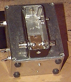
The inside of the unit without the meter circuit board. |
|
This circuit was in QST, June 2001 and can measure signals from about -70dBm to +13dBm by itself and up to +50dBm with an optional tap circuit. I refer you to that article for the schematic and authors' notes. This page is to simply display my construction layout and the inclusion of a small DC voltmeter for a digital readout. As you can see in the photos, I opted to attach the tap to the back of my enclosure which makes the meter and the tap one unit. I also used SMC connectors and a jumper to attach the tap to the RF meter circuitry. The analog meter can be switched in and out of the circuit, allowing for monitoring of voltages beyond its scale. The digital meter is set to a 20VDC scale. When I first turned on the meter I discovered that the digital voltmeter did not work when sharing the circuitry ground. Thus, I needed to add a second 9V battery to run the voltmeter separately.
|
|
Front panel showing the analog and digital meters. |
The inside of the unit without the meter circuit board. |
|
The partially built tap attached to the back of the meter. |
Completed tap circuit. |
|
Completed meter circuitry. |