AA3SJ
PT40
40 Meter Transceiver
This was my first attempt at putting together a few "pet" circuits to make a transceiver.
Special thanks to Mike, W3TS, and to Wes, W7ZOI, for helpful and much appreciated elmering.
Receiver
The Receiver is essentially a Progressive Receiver (Wes Hayward's "High Performance Receiver") with a few modifications.
The VFO is scaled downward to function at about 1.820-1.895MHz.
The IF has been changed to 5.18MHz. (I choose this frequency because I had a collection of matched crystals in my junk box.)
Receive input filtering is also different in my rig.
I added a 5K linear pot. in the receive line which serves as an RF attenuator to help control very loud signals.
About the only thing absolutely original to me, apart from the unique combination of circuits, is the 3 pole 500Hz crystal filter that I designed using Hayward's G87 and X filter computer design programs.
At this point the receiver is working very well and the homebrew 500Hz filter is performing as expected with reasonable rejection of the opposite side of the signals. Only very strong signals leak through.


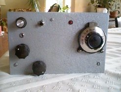
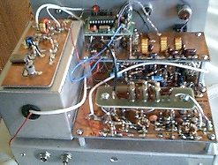
Photo of the completed transceiver (left) and the transmitter (right). The small board left of the transmitter, toward the front, is a sidetone oscillator.
Transmitter
The Transmitter is a modified MFJ Cub circuit.
I changed the bandpass filter between the mixer and the PA because the Cub utilizes tuned slugs which I didn't have in my junkbox. The schematic for the bandpass filter can be viewed with the link below.
I also included a simple 741 Op Amp sidetone oscillator.
I also replaced the final transistor in the original Cub schematic (2n5109) with a 2n3553. Maximum output is about 1.5 Watts, but I set the gain for a little over 1 Watt.
The 40673 dual gate MOSFET symbol is a bit artificial since my schematic drawing program didn't have a symbol for this "obsolete" device.
I incorporated a receive input filter designed by Marco Eleuteri, IK0VSV, published in SPRAT 105. IK0VSV's design works very well: Nominal 3dB bandwidth = 10% of center frequency, Nominal mid-band loss = 1dB, and Attenuation is greater than 60dB out of band.
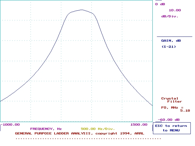
3-Pole 500 Hz Cohn Filter
I designed my own crystal filter for this rig. One of my goals I wanted to achieve was a practical understanding of crystal filter design. With W7ZOI's help and with his filter design programs, I built this circuit. The center frequency is 5.186 MHz. I matched my crystals to about 10 Hz. The computer generated filter specified 213pF capacitors, but I chose to use the standard value 220pF caps. This probably makes the filter a bit more narrow than 500 Hz.
3-Pole 500 Hz Cohn Filter Performance Graph
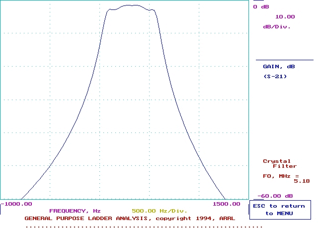
4-Pole 500 Hz Cohn Filter
The first crystal filter, referenced above, was a 3 pole filter. The 3 pole filter worked very well, but some of the opposite side of the signal could be heard with very strong signals. I couldn't resist testing a 4 pole circuit. After playing around with the computer programs, I discovered that a 4 pole filter used capacitors that were only 6pF higher than the 220pF caps I had used in the 3 pole filter. So, as a bit of an experiment, I simply added one more pole, using a matched crystal and the same capacitors. I was delighted with it's performance. Now I can still hear the opposite side of a very strong signal, but only with the IF Gain, AF Gain, and RF Gain turned to maximum. And, then, the opposite side is down in the noise floor and barely discernable.
4-Pole 500 Hz Cohn Filter Performance Graph
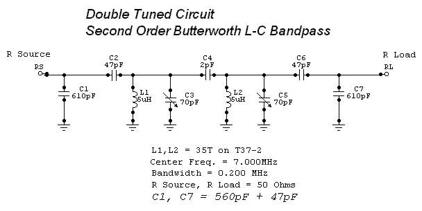
7 MHz Double Tuned Bandpass Filter
I designed this circuit using W7ZOI's DTTC, Double & Triple Tuned Circuits, computer program. The center frequency is 7.000 MHz with a bandwidth of 0.200 MHz. Source and load impedances are 50 Ohms. The filter uses standard capacitor values.
