AA3SJ
GCR2 Transceiver
General Coverage Mini R2 Receiver Incorporated Into A Transceiver
Synopsis
- A transceiver built around the Mini R2 receiver, designed by Rick Campbell, KK7B.
- General coverage receive from 1.8 - 30 MHz utilizing the IQPro DDS IQ VFO, designed by Craig Johnson, AA0ZZ.
- General coverage preselector using a modified preselector circuit originally designed by Mike Michael, W3TS.
- CW transmit coverage from 160 meters through 10 meters with a modified Updated Universal QRP Transmitter, designed by Wes Hayward, W7ZOI.
The Preselector Circuit
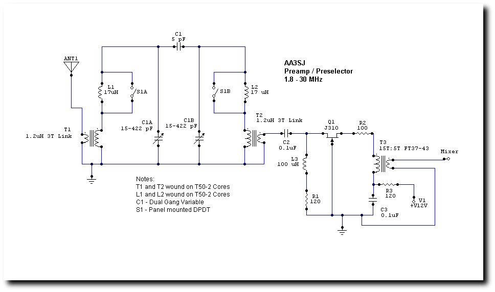
- The preselector circuit incorporates a double-tuned bandpass filter and a preamp using a J310 FET.
- With the components included in the schematic below, the preselector/preamp tunes from 6.795 MHz to above 30 MHz. Additional 17uH inductors (L1, L2) are installed in series with the primary windings on T1 and T2. With this additional inductance the preselector tunes from 1.8 Mhz to about 8.320 MHz. This was designed with a bit of overlap to insure continuous coverage from 160 meters through 10 meters. The DPDT front panel switch shunts L1 and L2 for resonance on 40 meters and above (although 40 meters will resonate with L1 and L2 in the circuit as well). The preamp was built using SMT components with the exception of the toroids and one resistor.
- The inductors and the variable capacitor need to be carefully matched for this circuit to work optimally. My capacitor has two attached trim caps (not visible in the photo) for fine tuning each section. I carefully measured the inductance of each toroid, squeezing the turns or adding/subtracting turns, before installation.
- A 3:1 reduction drive vernier is used on the variable capacitor since the preselector tuning is quite sharp. It is in fact so sharp that a slight turn either direction will completely eliminate all signals from being heard.
- Update (12/11/06): The preselector is optimized for 40 meters and up with the 5pF coupling capacitor between the stages. On 80 meters and 160 meters I can tune signals to a peak but the preselector would work better on these bands with a higher coupling capacitor. I clipped a 20pF cap. in parallel with the 5pF and noticed an improvement in signal strength. If you want to concentrate on these lower bands, you may want to experiment by replacing the 5pF cap with something larger. (I temporarily wired in a DPDT switch which toggles 5pF and 27pF coupling just to see how it would work, but I haven't done much listening with this configuration. You can see a photo of this preselector in the last photo in the receiver section of this page.)
- Update (12/12/06): I did some computer modeling of the preselector on 160 meters and determined that the best coupling capacitor would be right around 40pF. It provides a nice flat response with very little loss. I installed a 40pF cap on my switch and it does indeed improve performance considerably. Incidentally, the filter performance has a steep skirt below the cutoff frequency and a more gentle slope above it.
- Update (12/14/06): I did some computer modeling of the preselector to determine the optimum coupling for each band. (Click here to see the filter response graphs).
- Below is the schematic of the preselector/preamp.
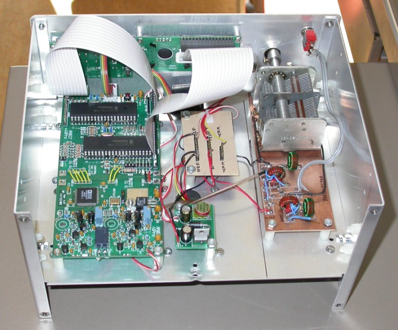
The "Almost Completed" Receiver
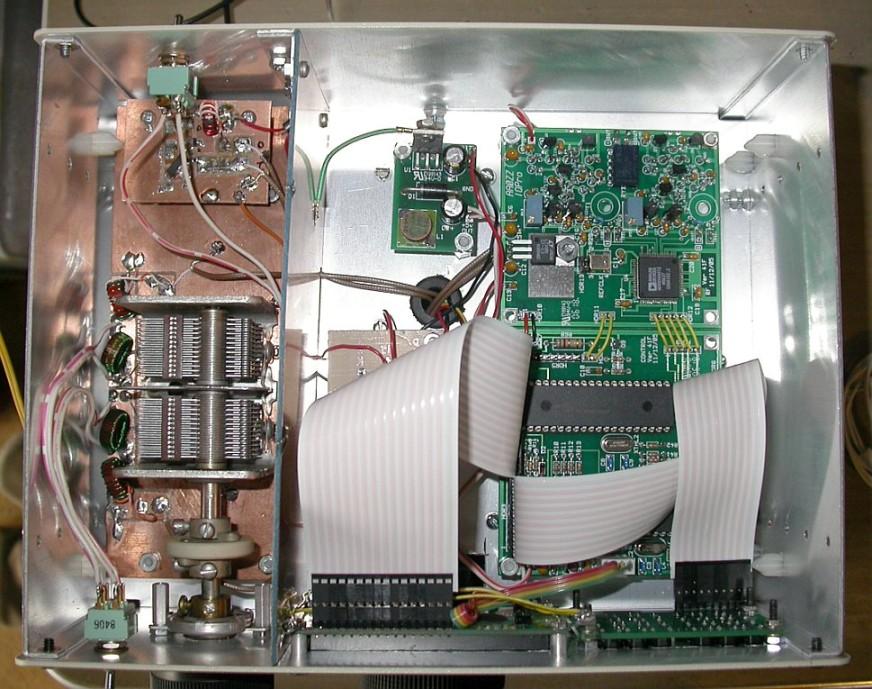
The following photos are of the completed RX stages. I mounted the DDS I/Q VFO on the top of the chasis partition alongside the preselector. The Mini R2 and filter board are mounted on the bottom. The boards are stacked with the filter board on the bottom. The filter board has three optional filters that are selected by a rotary switch on the front panel: 1kHz, 3kHz elliptical, and what KK7B calls "SSB Wide" which is actually the receiver wide open with a simple attenuator to control the gain. The extra standoffs are for the three transmitter boards: RF Amp, T/R Circuitry and Lowpass Filters (none of which are installed in these photos). The receiver, as presented here, is playing very well from 1.8MHz through 30MHz. Things to solve at this stage: I am hearing very faint noise when the encoder is turned and am hearing RF interference from the LCD backlight (not wideband noise, only on certain frequencies).
The Front Panel
Below is a photo of the front panel which shows the templates I made for the LCD and the 24 switch pushbutton array, both for the DDS I/Q VFO. Both templates are made of fairly stiff aluminum. One suggestion that I have, if the builder of the VFO wants to use the supplied PCB board for the switches (which is very nice) is to replace the supplied switches with ones with longer buttons. The ones supplied are very short and will not protrude through any template very far, making entry keying difficult. I simply bought the same model of switch but with a longer button from Digikey.
The controls on the front panel thus far are: Preselector Switch (top left), Preselector Vernier Drive (top left), Pushbutton Array (top right), Tuning Knob (center), Phone Jack (bottom far left), Volume Control (bottom center left), Filter Switch (to the right of the volume control), and Power Switch (bottom right, with LED indicator). The line on the bottom right is to align transmitter controls, when installed, with the RX controls.

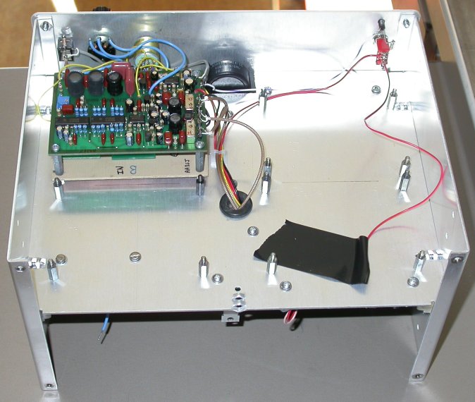
The Finished Receiver
After several days of listening, I've concluded that the GCR2 performs on a level rivaling the best receivers I have listened to. I have built a number of other Mini R2 receivers and this unit works better than any of its predecessors. Even while tuning very loud signals, the unwanted side of the signal is hardly noticeable. There have been a few component changes in the Mini R2 since I built my last one several years ago. Perhaps this accounts for the better performance. However, I think the excellent sideband rejection is the result of a very well matched output on the IQPro DDS. I carefully matched both the I and Q outputs with my oscilloscope. There were a few things I needed to tweak to satisfy my ears, however. Here are a few notes:
- I initially had to solve a problem of hearing what I thought was "encoder" noise. I would hear "ticking" as I tuned around the band. It turns out that what I was hearing was actually LCD noise. As the digits changed on the readout it produced a spurious noise in the receiver. This probably could have been avoided if I had built the entire RX on the bottom of my chasis rather than including the Preselector Circuit alongside the DDS VFO. However, the tuning capacitor needed more "head room" than the bottom of the chasis could provide.
- My solution to the LCD noise involved the following: 1) I grounded the bezel of the LCD which was painted black and I also directly grounded the LCD readout's ground plane); 2) I installed 100 uH RF chokes and 0.1 uF bypass capacitors on the Preselector, RX, and DDS VFO power leads (these changes removed about 95% of the noise) and 3) A shield made of PCB material was installed between the preselector and the DDS VFO. I can still hear "ticking" if I turn the audio gain very high and if the Preselector is not properly tuned to the band I'm listening on, but it is faint and not noticeable in general use.
- Update (12/11/06): In my receiver, I have discovered by trial and error that the encoder wiring harness is picking up the LCD noise. In my rig the best placement of the encoder wires was to tape them directly against the ground plane of the LCD. Any other place in the cabinet resulted in louder digital noise in the audio. I also discovered that the tab on the voltage regulator in the switching power supply was picking up some of the noise. The tab is at ground potential anyway, so I directly grounded it to the chasis for a noticeable reduction. Every little bit helps!
- The MiniR2's audio circuitry produces too much gain to provide comfortable listening in my 32 ohm Sony headphones. Thus, I installed impedance matching resistors to tame the audio at the phones. This simple circuit consisted of a series 1k resistor shunted by a 33 ohm resistor on the audio output. The gain is now tolerable, but still high. A 1.5k resistor may have been a better choice. (This also helped to tame the spurious VFO noise.)
The photos below show the completed RX installed in its Ten Tec enclosure. As you can see, I choose to change the original vernial dial, opting instead for a reduction drive unit installed inside the cabnet. (W3TS was strongly opposed to the "cheap-looking" vernier that I originally used!!)
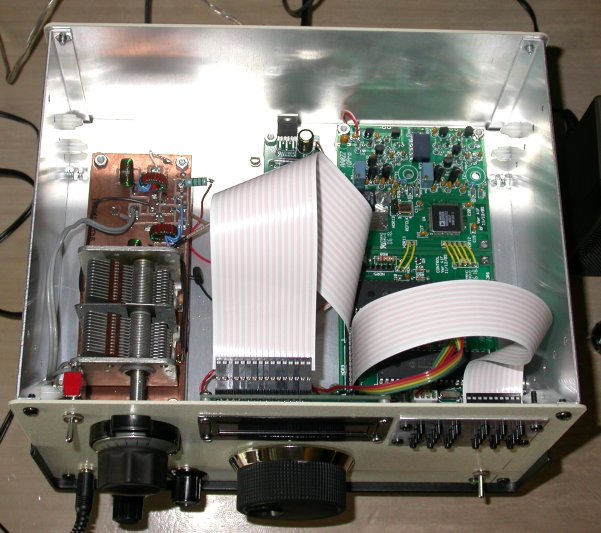
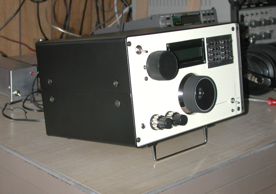
And finally, here's a photo of the inside of the top of the rig as it exists currently (12/12/06). This photo shows my final wire placements, and the shielded preselector.
The Transmitter
(Click this link to go to the transmitter page.)
