
Background Comments
I own an Yaesu FT-817 that I wanted to use on 6 meters but none of my antenna tuners could match my antenna setup for that band. My antenna is a "maypole" dipole arrangement: 80m, 40m, and 20m half-wave dipoles fed with a single coax feedline. After searching the internet I was unable to come up with any 6 meter antenna tuner circuits, so I decided to experiment and design my own. After all, if MFJ could do it, so could I. It was more fun to build my own than buy one of theirs.
First Attempt
My first attempt was a simple T-Network circuit, using two 14-250 pF variable capacitors and a 0.2 uH air wound coil. The coil was constructed using #14 solid copper wire wrapped around a 3/4" bolt (0.2 uH = about 3 - 4 turns). I housed the circuit in a plastic enclosure to reduce stray capacitances. This tuner was indeed capable of matching my antenna to a 1.0:1 SWR throughout the entire 6 meter band (and even worked on 10 meters). However, hand capacitance was severe enough at 50 MHz to be quite troublesome. At 28 MHz hand capacitance was minimal. The schematic of this circuit is shown below.
Second Attempt
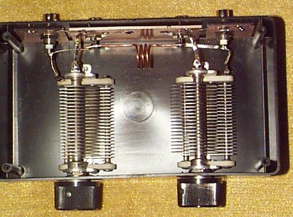
On a whim, I decided to rewire the T-Network to a PI-Network using the same components. This time hand capacitance was obviously minimal because the rotors of both capacitors were grounded. Surprisingly (to me anyway), I was able to get a 2:1SWR at 50.100 MHz. I noticed that if I increased the spacing of the turns on the inductor (initially 4 turns of #14 copper wire) the SWR decreased. After removing one turn I was able to get a 1.0:1 match across the entire 6 meter band. However, I could no longer get a good match on 10 meters. The components I used are large enough to handle QRP levels and at least up to 35 watts which is the output of my little 6 meter amp that I sometimes use with the FT-817. I settled on this circuit for now. The PI-Tuner is the first schematic shown below and is also shown in the photo.
Conclusions
After matching my antenna to a 1.0:1 SWR I measured the capacitor settings: 77pF on the TX side and 36pF on the antenna side. Clearly, I did not need to use capacitors that extend to 250pF. I simply grabbed two matching caps from my junk box. Your results may vary depending on your antenna arrangement, but this may at least give you a starting point for experimenting. If you come up with other useful designs please email me a description.