14 El. DK7ZB yagi antenna for 432Mhz
The purpose of this page is not to repeat the same what can be found on the original DK7ZB pages but to present some mechanical and electrical solutions that can be useful for the Hams. All dimensions of the antenna can be found on the DK7ZB home web site and they will not be repeated here.
Aluminum material that I used for this antenna is the scraped old Tv antenna. Boom is consisted of three light pieces just above 1 meter in length reinforced by U shaped lover part of the boom, where the mast bracket is mounted. This solution give us a lot of flexibility for portable, mountain operation. All elements are attached to the boom with already well known method (plastic insulators and 3 mm screw). This part of construction is not so critical and can be done very quickly. Of course, you should pay the attention to the length and position of each director and reflector. I build the antenna using 10 mm Al for the directors/reflector and 12 mm Al for dipole. The only time consuming part is modifying existing insulators or building the new ones from the plastic pipe. If you have original Wimo insulators your antenna will be assembled very quickly.
Impedance
Velocity %
Capacitance
Attenuation
Average Power
Max.operating temp
75 +/- 3 ohms
69.5
15.4 pF/Ft
16 dB/100Ft @ 400Mhz
189 W cw @ 400Mhz
200 'C
Up to this point, there should be no difficulties. The only tricky part that remains is Dipole with Match. Just follows the measures for the dipole length, and almost no correction should be done later. The center distance between the dipole parts is 5 mm on my antenna. Use the quality material for the center insulator. Dipole is housed in waterproof electrical plastic box together with the Mach. Radiation resistance of the dipole is between 25-30 ohms and Mach to 50 ohms is required to achieve SWR close to 1:1. For this purpose we are using two parallel connected quarter length 75 ohms coaxial sections. Between several types of coaxial cables if prefer to use RG-179. RG-6, RG-11 together with TV coax is quite rigid and not easy to install in a small plastic housing. On the other side, RG-179 can fit easily in the box and there is less problems due to heating during the soldering of the teflon coax type. 
In the small table beside you can notice some basic RG-179 characteristics. Constant impedance, and velocity factor will give us the length of 120 mm for the teflon type coaxial cable. This is the length of the shield without connecting leads which should be kept as short as possible. One side of the match should be connected directly to the dipole and the other side on the antenna connector. As you can notice on the photos below, the mach is symmetrically centered in the box not to affect the dipole resistance and to minimise the possible mismatch.
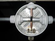
You can also notice on the photos below that I used UHF coaxial connectors in the antenna box. This is bad example and you should always avoid this UHF connectors on the frequencies 432 Mhz and above. Amphenol stated that the maximum operating frequency is 300 Mhz with unstable impedance, so they are not good for the 432 Mhz. Instead, I recommend the N type connector which is good for this purpose, watertight, stable 50 ohm impedance and low loss on this frequencies. (Loss (dB) = 0.05 x f (Ghz)). They are handling even more power and you can run your legal limit power on this band too. The only limitation factor for running the high power is the 
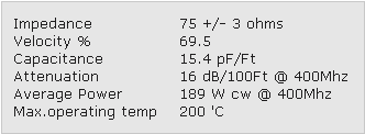
coaxial cable that we are going to use for the matching section. Limit power for the RG-179 is 189 W continuous @ 400Mhz. As we are using two pieces connected in parallel so the maximum power can be around 380 watts. I test my antenna in the contest with 350 watts and no problems found at all. SWR was stable.
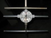
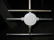
At the end, just one more hint, do not forget to ground the coaxial N connector on the dipole side. You can notice on the photos a small L aluminum profile grounding the N connector with the screw going through the plastic antenna box to the boom.
Home