Gi7b is tube designed for microwaves but working good as HF amplifier. Idea was to built cheap, reliable HF amplifier covering 160m.
Parts
Tubes
Russian
impulse triodes Gi7i are cheap rugged tubes. Original anode coolers was replaced with hi power rectifier coolers
which perfectly fit and allows better cooling by easy-to-find axial blower.
Slightly cooling of cathode also should be provided.Gi7b shows excesivecathode overheating in case of
insuficient cooling.
Switches
Mayor problem was band switch.2 pole 9 throw ceramic switch from
Surplus Sales of Nebrasca was look like good option but unfortunately
burned out during tune up.
Huge spark burned 17m switch during 40m band tuning.
Open gaps on anode L acts as autotransformer taps and high AC
voltages appiers on higher ends and make sparks to closest common.
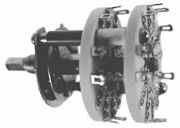
Many sigle pole 6 throw switches in my junkbox enforced me to use them in this PA.
This switches are from General Electrics BCs made in WWII for US Army Signal Corps. and
picked up from military surplus.Heavy duty switches like everything from good old days.
It is imposible to cover all 9 HF bands with 6 throw switch so WARC bands waiting for new
opportunity.3 switches are used .First for adding capacity to plate condenser,second for taps
on tank coil and third for adding capacity to load condenser.
Condensers
Variable condensers are air type and also picked from junkbox.Values are not critical because of
additonal switched condensers.Of course,take care on spacing of plate C.
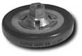
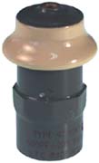
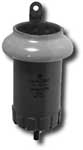
Additional plate caps working hard job and need much more care. You should find HV caps with
good current capabilities and proper capacity, of course. Maximum voltage and capacitivity are
written on body of capacitor but current isn't in many cases. Easiest way is to choose caps with screw
terminals and heavy body. Few types below....


160m band is hardest challenge for additional plate caps. If your caps blow out or change color during
transmitting it is good sign that you didn't choose good one. Also you can see mistuning due to overheating and changing capacity.
Usage of 2 or 3 parallel caps instead one is good way to obtain good current capability.
Coils
Common opinion is that silver plated wire is best choice for tank coil but it isn't reason to give up if you haven't
access to that kind of wire. Common Cu wire is good enough and copper tube working just fine on 10m.
There is lot articles about anode-choke and how to calculate proper choke. Due to reduced sources of chokes
I was enforced to use some kind of reverse engineering i.e. to wound anode-choke on any available body.
So, I just wound CU wire on ceramic body to fit. It was lucky shout although XL of choke seems to be little low
for 160 it works fine, without visible losses or arcing.
Chassis
HV power supply and RF deck are in two separate boxes. PS have soft start circuit, HV
transformer, rectifiers and filter condensers.
RF deck consist input circuit, tubes and output circuit.
Idea was to make cheap, easy to built amplifier.
Chassis should to be make for easy approach to every part of amplifier even if that means
bigger case. Also, huge case allows good cooling.
Cathode circuit
Cathode is direct-driven. Input impedance is about 100 ohms or less i.e. SWR is 1:2 or less. Input SWR
is in direct relation with output circuit tuning and and you have minimum SWR with optimum tuned output.
1:2 SWR is piece of cake for transceivers with tubes in final and also for modern built-in tuners.
Transistor final transceivers without tuners will deliver enough power for driving this PA although ALC will decrease RIG's power. 60W is more than enough drive power.
If you have transistor transmitter without ALC circuit you should consider about matching circuit. Common antenna match-box will be good for this purpose.
Anode circuit
is PI network calculated for covering all bands (WARC excluded) with available parts.
Biasing
Lack of power Zener diodes enforced me to use power transistor instead. PNP transistor is easy to mount
on proper cooler direct on chassis, without isolation. You should obtain 80mA of idling current. This value
depends on both anode and grid voltage. It's hard to change voltage of mains and easy way is to change grid voltage. In original PA 12 throw switch is used for switching 12 Zener diodes in 3.3 V steps. It means that
first diode is 3.3,second 6.6 etc. These diodes is serial connected with an 30V diode.
If you intend to use your PA only in one place with stable mains you could put just one proper value diode
(around 39 V) between base of transistor and 56V blocking diode.
56V (or more) Zener diode is switched with 1b contact of REL1 when PA is in transmit mode.
Wires should be short and RF blocking of transistor terminals and diodes are recommended (with 1n/100v)