Cryptic letters on the right side are codes for
Japanese/Chinese characters.
The handwritten schematics revived.
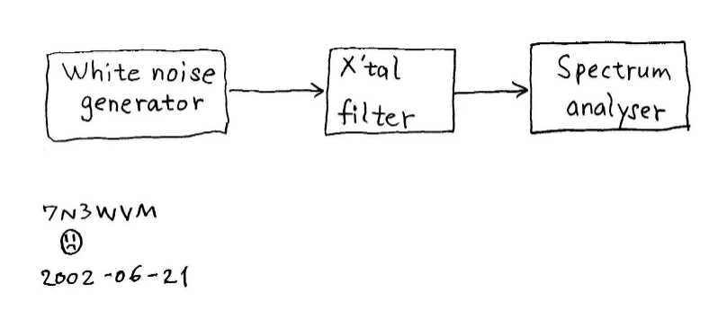
| What do you do when you want to measure your homebrew crystal filter? If you happen to have a spectrum analyser then a possible shematic diagram could be the following. | 自作のクリスタルフィルターの特性を測定したいとき、スペクトラムアナライザーを持っているならば、次の図のようにしてはかることができます。 |
| What if you have no spectrum
analyser, just like me? Here is a trick to do it with a
PC. I found a free FFT software program which makes your
PC function as a spectrum analyser. Yes, it is not for
the radio frequency but only for the audio frequency.
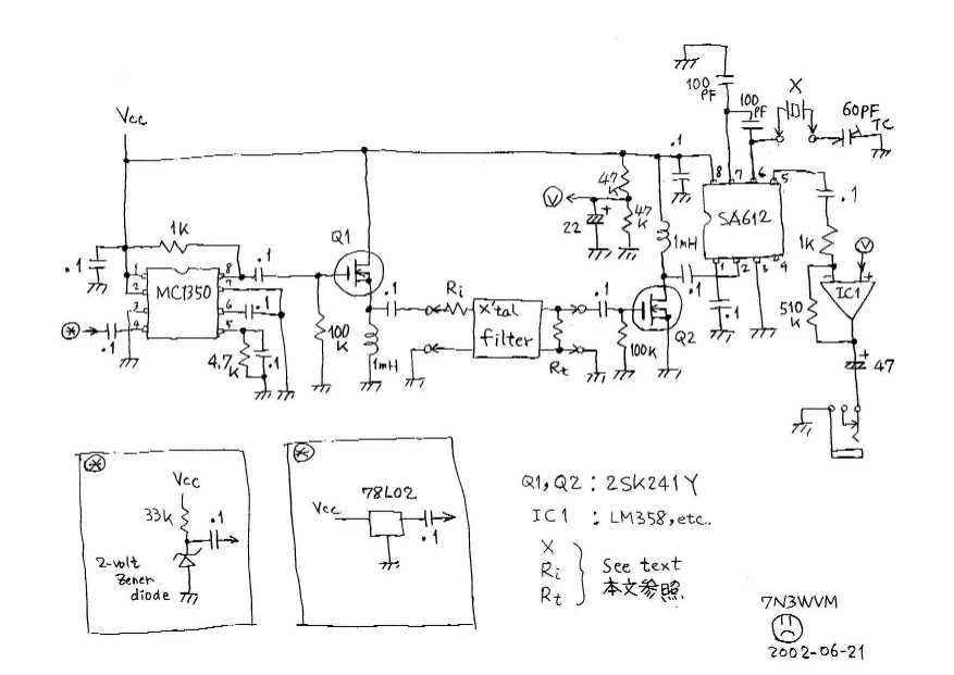
What shall we do? Superheterodyne down conversion as shown in the next figure is the solution. Assume you built a ladder filter with sveral pieces of crystals with an identical frequency. If so, take another piece of crystal of the frequency and make a local oscillator with it. The local oscillator frequency is then a bit higher than the upper edge of the filter's pass band. Then the pass band RF frequency is down converted by a mixer to audion frequency band which you can deal with by the PC spectrum analyser. |
スペアナを持っているならば苦労はしない・・・。でもなくてもだいじょうぶ、音声周波数帯域で使えるパソコンのスペアナソフトが役に立ちます。次の図のように局発とミキサーでクリスタルフィルターの通過周波数帯域を音声帯域に周波数変換してやります。 自作する場合ラダ-フィルターが多いと思いますが、フィルターに使ったのと同じ水晶発振子で局発を作ればその周波数はフィルターの通過帯域の上端よりちょっと高い周波数になります。その結果、ミキサー出力は丁度音声周波数帯域になります。 |

| Here follows a schematic
diagram for the circuit. As mentioned above, The crystal
X for the local oscillator is the same crystal as is used
in the ladder filter. R i and R t are
the resistors for the impedance matching. taking R i = Z i-100ohms and R t = Zo should be roughly OK, where Z i and Zo are the imput and output impedance of the filter, respectively. The key of this circuit is the white noise generator. If the level of the white noise is not enough, then the measurement gets not reliable. Two possible white noise generators are shown as examples in the insets, where a zenner diode and a voltage regulator are used, respectively. Maybe 78L02 is a bit hard to find, but you can also use 78L05 if you use higher Vcc. Any other commonly used noise generator could be tried as well. You had better repeat trial and error to get the highest noise level. To the contrary, Q2 and IC1, being on the output side of the filter, should be low noise devices in order to keep the noise floor as low as possible. |
回路図はこんな感じです。上に述べたように局発用の水晶はラダーフィルターに使ったものと同じ物を使います。インピーダンス整合用の抵抗として、フィルターの入出力インピーダンスをそれぞれZ
iとZoとして、おおざっぱですが R i = Z i-100ohms R t = Zo とすればよいでしょう。 この回路でホワイトノイズ発生器のノイズ強度が十分でないと、測定はうまくゆきません。挿入図の2例以外にも可能なものはあると思います。78L02のかわり78L05を使うときはVccを高くしたほうが良いでしょう。もっとも強いノイズが出るように試行錯誤が必要です。その反対に、フィルターの出力側のQ2やIC1は低雑音の素子を使う方がよい結果がえられます。 |
| You connect the output of
this circuit and the line-input of your PC. I use the FFT
program called WaveSpectra
coded by efu
available free on the internet. Unfornunately the
program is made for Japanese language only, but I am
certain you also have the similar thing out there made
for your own language(WaveTools
might be the English analogue. I am not quite sure,
though). Then you may need to set up your sound card to
activate your line-input for the WaveSpectra before you
start the measurement. Please refer to the instruction
manual of the program for the detail of the measurement. The following is the result of the pass-band measurement of my homebrew 4-element ladder crystal filter made of 3.575MHz crystals. It is actually an average of 100 FFT measurements. |
さて、この回路の出力をウインドウズパソコンのライン入力に接続します。音声周波数帯域用スペアナソフトとしては、efu
さんの作られたフリーウェアWaveSpectraを使いました。他にも同様なソフトがあると思います。あとは、サウンドカードの必要な設定などをして、測定開始です。測定法の詳細はWaveSpectraのヘルプを参照してください。 次の図は、3.575MHzの水晶発振子を使って自作した4素子ラダークリスタルフィルターをこの装置で測定した結果です。100回の測定の平均で示してあります。 |
| Note that the origin of the
scale on the abscissa has no meaning because the
frequency has been down converted. However, the pass-band
width is correct. In the above case, it is something like
350Hz; it depends on the definition which I do not care
this time. Besides the pass-band width , correct is the
ripple of the flattop. How about the ordinate? The pass-band attenuation, about -30dB in this case, has no meaning either. If you want to know the attenuation, then you have to measure the reference level by replacing the filter with the 0-dB jumper wires. The top-bottom ratio, something like 50dB in this case, could be not very correct if your white noise generator is weak or your post-filter circuit has non-negligible noises. Last but not least is tha fact that USB and LSB are reversed in this measurement because the local oscillator frequency is higher than the pass-band of the filter. Although there are some shortcomings as mentioned above, I would say it is a nice easy method because the pass-band width and the flattop ripple can be measured reliablly. Are these two parameters what you actually wanted to know in hombrewing your ladder filters? BTW, you may want to know how I designed the ladder filter. Visit the pages of JA9TTT for it. Again, they are written in only Japanese language(*). Why don't you start with learning Japanese first of all? (*)JA9TTT now added a machine translation utility in his page for foreign visitors. |
横軸の目盛りは周波数変換した結果ですから、相対値のみが意味を持っています。上図の場合の通過帯域巾約350Hz(定義によって異なります)は信頼できる数値です。また頂上のリップルの様子も正しいものと考えられます。 縦軸の数値はどうでしょうか?頂上と底の比約50dBというのは、大体信頼できますが、ホワイトノイズ発生器の出力レベルが低かったり、フィルターの後の回路の雑音が大きい場合にはこの比が怪しくなります。また、頂上部の減衰約-30dBというのも無意味な数値です。本当の減衰を知りたければ、フィルターを無減衰のジャンパー線で置き換えて測定したものと比べてやる必要があります。 最後に重要なことは、局発周波数がフィルターの通過帯域よりちょっと高い周波数になっているので、測定した特性のUSBとLSBが本当のものとは逆になっていることです。 このように少し欠点もありますが、本当に必要な通過帯域巾と頂上のリップルがちゃんと測れるのですから、まあよしとしましょう。 ラダークリスタルフィルターの設計法についてはJA9TTTさんのよいページがありますので見て下さい。 |