Construction of a Rockmite.
The Rockmite, from
Small Wonder Labs
, is one of the various minimalist QRP Amateur Transceivers available in kit form. The Kit was
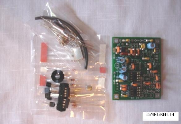
ordered on the 16th of March, 2006, and arrived in Nairobi on the 07th of April, well packaged. I
found all in Board PCB components as specified in the instruction manual, expect the mixer IC which
was supplied as SA/NE612, in place of a SA/NE602, and started building it on the 8th. The output
power is specified as 0.5W from a 2N2222A, which could provide useful contacts with stations in the
2000-8000KM range, under good propagation conditions. The TX is crystal controlled, and the RX is a
DC type, which uses a SA/NE602/612 for mixing. There is a preprogrammed PIC controller that
provides T/R switching, Side-tone, and Iambic CW. The AF section uses a dual 1458 Op Amp. The kit
can be built, and put on the air over night, but it is wise to task the assembly of electronic
parts. I am looking forward to using The Rockmite on the 20M QRP frequency.
Above: The Rockmite about 1 hour into construction(SMD, IC Sockets, and Capacitors).

Above: The completed Rockmite in a Mitybox , with connectors and controls (June, 30, 2006).
Very little troubleshooting was required to put the Rockmite on the air. On a coax fed 20M horizontal dipole at about 30ft, QRP CW stations in North America, can be heard after about 20:00UTC, while Europe can be heard most evenings(15:00UTC-21:00UTC) around the 20M QRP calling frequency. There is some MW BC QRM during peak evening DX hours at my QTH. Addition's to the Rockmite setup, that will help improve its performance include adding, a 1:1 Balun at the feed point to the dipole center, an Antenna Matching Unit to provide optimum SWR, and an active audio filter to improve RX selectivity. I am also considering a change to the PA transistor(Q6) to output about 1W, to make intercontinental QSOs more realistic.
Following are popular modifications to the Rockmite to enhance its experience.
1. The RX front end is weak if an AM Broadcast band transmitter is nearby, and the Direct Conversion RX will experience interference. While this issue
may be solved by using a balanced antenna system, a more direct approach would be to use the RX RF BPF front-end modification below.
Consult the Rockmite 20 schematic avaialable from the Smallwonder labs web site. Remove C1, Y1, and C2, and build the circuit above on a PCB or perforated board.
Use minature cylindrical crystals for Y2, and Y3 available from, Expanded Spectrum Systems.
Replace the original C1 with a 27pF multilayer ceramic(COG) capacitor, use another 27pF capacitor for C2 above. Use sub-minature confromal coated epoxy RF inductors for L1, and L2.
After building the above circuit, solder using short runs of hook-up wire to the Rockmite PCB as shown above,
to the D2 pad of the original Y1, U2 pad of the original Y1, and ground pad of the removed C2.
Another method to solve the Broadcast band interference is to use a narrow band Butterworth or Chebyshev 20M Band pass filter centered on 14.060MHz with at least 3 elements before the Rockmite input.
You will also find that you can use a 3.3uH value for L1, and L2, and 39pF for C1, and C2. If the circuit board you use is small enough, you will also find you can squeeze the new modification board just above
the position of Y1 or to the side flash on a Mitybox enclosure. Avoid electrical shorts by using insulating tape or self-amalgamating tape.

2. Rock bound is fun, and many have made Rock bound to Rock bound QSO'S with great success,
but many of us find a VXO would be covnienient to increase the chances or working more stations around the QRP calling frequencies of a Rock bound mite.
Another popular modication is to add VXO to the Rock. Below is a typical circuit.

R1, R2, R3, and R4 are 0.25W values C1 is a multilayer ceramic capacitor. D1 is a 8.2V zener diode. R5 is a 10K linear pot.
L1 is a 4.7uH conformal coated epoxy RF inductor. D2 is MV209 a 32pF variable capacitance diode.
Again you can build the circuit on a perforated strip board or design a PCB .
You will find you can use a 3.3uH value for L1 and experiment with D2 for greater coverage.
Consult the original Rockmite 20 schematic, then remove R9, R10, and D5, and D6 from
the Rockmite PCB, next connect from your completed modification PCB, using short runs of hook-up wire, +V to the +V pad of R9 on the Rockmite PCB,
G to the anode pad of D5, Q2 to the cathode pad of D5, and Y2 to the cathode pad of D6. If you added the 1M volume control to the Rockmite,
and are using a Mitybox, remove the 1M pot, and re-insert a 470K to 820K resistor in the R5 pads,
then you can use the Mitybox pot pre-drilled hole for the VXO pot control control.
Both above modifications will squeeze fit in the Mitybox, if consideration was taken in the design of your modification perforated strip board or custom PCB.
In place of the above VXO modicications as above, you can try implementing the HIMITE VXO circuit in the Rockmites as shown in the schematic below. Consult the
Rockmite schematic for your band of use, then remove Q2(Static sensitive), R9, D5, R10, D6.
Construct the Himite VXO modification on a PCB or perforated prototype strip board. Use a 26pF-50pF varactor/varicap diode such as BB204 or MV209 or even an SMD MMBV609, the reduced
value resistors should give you coverage as in the original HIMITE design. Once your VXO is complete connect using short runs of equipment wire, 3U1 to pin 3 of U3, 1U1 to pin1 U1,
+V(R9) to the supply pad of R9, and Y1 to the now unconnected pad of Y1. Your Rockmite should now work similar to the HIMITE. With these modifications you would have to use a larger enclosure than an Altoids tin for your
enhanced Rockmite.
3. Yes, the Rockmite is a QRPp transciever, and DX contacts have been made using the milliwatt power, you will find though that at least one of the station's that made the QRPp DX contact had a type of high gain HF antenna, most people like to see how far the Rockmite signal will go using wire antennas. Realistically, to use a good wire antenna you need 0.75W to 1W out of the Rockmite. So a popular modification is to replace the output transistor Q6 with a pin compatible high power or medium power transistor like a 2N3053. If you use a 2N3053 change R18 to 6.8 Ohms which should give you about 0.8W from a 9V supply, you can also choose to use an RF tranisistor like 2N5109, but use a 2.7 Ohm resistor for R18 here, to give you about 0.8W from 9V. If you increase the power of a Rockmite beyond 1W you may have problems with emissions, as the Rockmite was never deisgned to exceed 1W. Do not operate the Rockmite with R18 shorted. 0.8W RF output modifications allow you to use an external QRP power amplifier like the NORCAL Miniboots for a full QRP galllon of 5W.
4. The Rockmite AF out-put is rather broad, and at QRP levels a QRO station next to a QRP signal you are trying to read can make copy difficult. A worth-while addition is an external band-pass active audio filter like the Bramwell variable audio filter(See ARRL HB 1997 page 16.33), and Nescaf capacitor network audio filter.
5. Once you got your Rockmite going, you may find that you want more functionality from the PIC keyer. RM Keyer upgrades are available from Hamgadgets (RM Pico keyer), and Jackson Harbour Press(RMK).
6. Operate your prize QRP show piece gem on a balanced antenna system using a balun , and Norcal Balanced Line Tuner or DL QRP Project ZM-4.