Xnec2c is a GTK3-based Graphical version of nec2c, my translation to the C language of NEC2, the FORTRAN Numerical Electromagnetics Code commonly used for antenna simulation and analysis. The original nec2c is a non-interactive command-line application that reads standard NEC2 input files and produces an output file with data requested by "commands" in the input file. In contrast xnec2c is a GUI interactive application that (in its current form) reads NEC2 input files but presents output data in graphical form, e.g. as wire frame drawings of the radiation pattern or near E/H field, graphs of maximum gain, input impedance, VSWR etc against frequency and simple rendering of the antenna structure, including color code representation of currents or charge densities. These results are only calculated and drawn on user demand via menu items or buttons, e.g. xnec2c is interactive and does not execute NEC2 "commands" in batch style as the original does. Printing of results to an output file has been removed starting from version 1.0, since xnec2c works in a way that does not allow printing compatible with the NEC2 format. If printing to file is needed then it is better to use the original NEC2 program, to avoid bugs that may still be lurking in the C translation.
Xnec2c now has a built-in editor for NEC2 input files which can be used to edit geometry or command "card" data. This basic editor displays comment, geometry and command cards in tree views where individual rows, each representing a card, can have their cells edited directly for "raw" entry of data. More useful are pop-up "editor" windows that open when appropriate buttons are clicked or when a selected row is right-clicked with the mouse. These editors allow easier, more convenient entry and editing of individual rows, with no need for detailed knowledge of "card" formats. When editing is completed, the contents of the nec2 editor can be saved in a NEC2-compatible input file which can then be re-loaded by xnec2c for execution.
2. Features:Interactive
Operation:
Xnec2c is interactive in its operation, e.g. when started it just
shows its Main window in a "blank" state, indicating that no valid
input data has been read in yet. The NEC2-type input file can be
specified at start-up in the command line optionally with the -i
option or it can be opened from the file selection dialog that
appears via the File->Open menu of the Main window. Once a valid input file is opened,
all the normal widgets in the Main window
appear so as to allow proper operation. The NEC2 "commands" in the
input file are read in but not executed, until a request is issued
by the user via buttons or menus in the appropriate windows.
No Output
File:
Printing of results to an output file has been removed starting
from version 1.0, since xnec2c works in a way that does not allow
printing compatible with the NEC2 format. If printing to file is
needed then it is better to use the original NEC2 program, to avoid
bugs that may still be lurking in the C translation.
Color Coding:
Xnec2c uses color coding to visualize the Current or Charge
distribution in the Structure's segments or patches as well as the
Gain pattern or the Near E/H field pattern. Color coding is also
used to clarify the Graphs of Frequency-related data. A color code
strip is shown in the Main and Radiation Pattern windows.
On-demand
Calculation:
Since xnec2c collects data to be displayed in buffers directly from
the functions that produce them, there is no need to produce and
parse an output file and no need to re-run the program when certain
input data (currently the frequency) is changed or when different
output data (gain, near-fields, input impedance etc) is required.
The frequency can be changed either from spin buttons in the
Main and Radiation Pattern windows or by clicking on
the Frequency Data window's graph
drawing area. The frequency corresponding to the pointer position
will then be used to re-calculate whatever data is on display.
Multi-threading
operation on SMP machines:
Since version 1.0, xnec2c can run multi-threaded (by forking) on
SMP machines, when executing a frequency loop. Multi-threading is
enabled by using the -j<n> option, where n is the number of
processors in a SMP machine. xnec2c will spawn n child processes,
to which it will delegate calculation of frequency-dependent data
for each frequency step. Thus data related to n frequency steps
will be calculated concurrently and passed on the the parent
process by pipes, to be further processed for graphical display.
Child processes are spawned before GTK is initialized and started
so that only the parent process is tied to the GUI interface. Thus
there are n+1 processes running when the -j option is used and
execution is faster by slightly less than n times. Please
note that its pointless and counter-productive to specify a
value of n greater than the number of steps in the frequency
loop.
Built-in NEC2 input file
editor:
Xnec2c has a built-in editor for NEC2 input files. Data in NEC2
"cards" can be entered or edited either directly in the main editor
window (tree view) or in more convenient dedicated editors for each
type of card. Edited data can be saved to a NEC2 input file and
reloaded for execution so that the edit-execute-display cycle is
quicker and more convenient.
Since xnec2c is interactive, it cannot operate in the same way as NEC2 or nec2c. Specifically, commands that cause execution in NEC2/nec2c (XQ, RP etc), are only read in but not acted upon unless the user requests the display of relevant data. For example, if an RP command line is included in the input file, xnec2c reads the relevant data from that line but does not calculate/render the radiation pattern, until the user requests this by opening the Radiation Pattern window and clicking on the Gain button. In addition, the NX and WG/GF commands are not recognized since only one structure at a time can be input and evaluated, and the Numerical Green's function is not needed or implemented. Also, some options of certain commands (e.g. the surface wave option I1=1 of the RP command) are not implemented and they must not be used since they will disrupt or even crash xnec2c.
There are advantages deriving from the interactive operation: it is possible, for example, to specify both the NE and NH commands in combination with a multiple-frequency FR card, although only the relevant data of the last command will be used.
4. Compilation and
Installation:
Please note that I use Void Linux
AMD64 which is a "bleeding edge" type distribution, so there
may be compilation and/or run time difficulties if you are using a
relatively old distro. This is mostly true of the basic
dependencies like GTK+-3, and there can also be sound card
incompatibility problems at run time.
To compile the package, it may be preferable to first run the included "autogen.sh" script in the package's top directory, to produce a fresh build environment. Then the "configure" script can be run with optional parameters to override the default settings and compiler flags, e.g: ./configure --prefix=/usr CFLAGS="-g -O2" will override the default /usr/local installation prefix and the "-Wall -O2" compiler flags.
Running "make" in the package's top directory should produce the executable binary in src/. Running "make install" will install the binary into /usr/local/bin by default or under the specified prefix. It will also install the default configuration file into the user's home directory. This will have to be edited by the user as required. There is also this hypertext documentation file which you can copy to a location of your choice.
No configuration files are needed and the sample input files that were used during development are in the xnec2c/examples directory. Please also read the xnec2c/doc/nec2c.txt file that describes the nec2c application that is used as the basis for xnec2c.
5. Operation:Command Line
Options:
Xnec2c has the following command line options:
-i <input-file-name>: Specify a NEC2 input file to be opened at start-up. If the -i option is omitted, xnec2c will take the last argument to be the input file path name, but will only open it if it has the .nec extension.
-j <number of child processes to spawn>: Since
version 1.0 xnec2c can run multi-threaded on SMP machines. This
option specifies the number of child processes to spawn by forking,
so that the total number of processes running will be n+1. n should
be equal to the number of processors in a SMP machine. Please
note that its pointless and counter-productive to specify a
value of n greater than the number of steps in the frequency
loop.
-h: Print usage information and exit.
-v: Print version information and exit.
Note: As of version 3.7-beta, many buttons and menu items have been given keyboard accelerators and these are denoted in brackets, after the mention of these widgets in the manual's text.
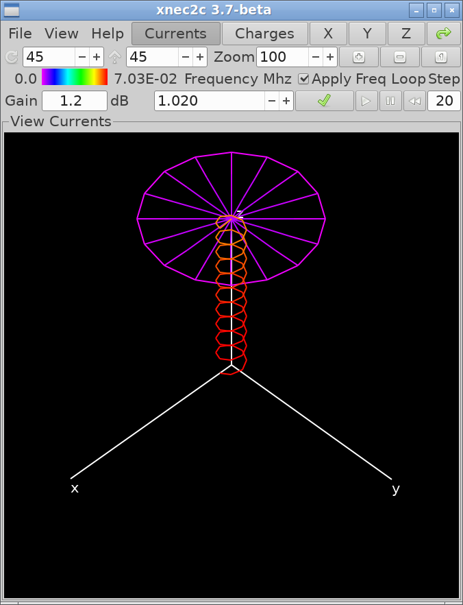
When starting xnec2c from a terminal or from a file manager (by OLE), the -i option can be used to specify a NEC2 input file: xnec2c -i ~/nec2/turnstile.nec. Otherwise an input file can be opened from the Main window's File->Open (o) menu item. If the input file is valid, xnec2c will render the structure specified in the Geometry section of the file in the Main window's drawing area. The background color is black and the structure is rendered in blue. The excitation points (segments) are rendered in red, the x, y, z axis in white, loaded segments in yellow, transmission lines in cyan and two-port networks in magenta. These colors are hard-coded in the source code and at this stage of development there is no option to change them.Once an input file is opened, the structure display can be rotated around the Z axis and tilted about a horizontal axis through the origin. This can be done either by pressing button #1 and dragging the structure with the mouse pointer, clicking the X (x), Y (y), Z (z) or the right-arrow Default (d) view button (45 deg rotation and tilt). The actual value of rotation and tilt is shown in two spin button widgets which can also be used to change the viewing angle.
Starting with version 2.1, the structure display can be zoomed in or out by using the mouse wheel or the Zoom controls: Zoom % spin wheel and the + (Ctrl Key +), - (Ctrl Key -) and 1 (Ctrl 1) buttons and it can also be moved around by dragging with the right mouse button #2.
The current distribution or charge density in the structure can be displayed by clicking the Currents (i) or Charges (v) toggle buttons at the top right of the Main window. The distribution of current or charges is rendered by a color code, red for the maximum value and magenta for zero. The Frequency Loop control buttons can be used to Start, Pause or Reset the loop. There is a Color Code bar at the left of the second row of widgets in the Main window, indicating the color coding and the maximum value of the displayed quantity (at its right).
The title in the border of the drawing area widget shows the user-selected function of the display, while the text entry widget at the right of the color code bar shows antenna gain in the Viewer direction, e.g. perpendicular to the Screen. To the right of this the Frequency Spin Button shows the current frequency in MHz for which the current/charge distribution and Viewer gain are calculated and displayed. If the Redo Check box is active, each time the frequency is changed in the spin button, all relevant data on display will be recalculated. If not, clicking the Redo button will initiate recalculation.
Printing of results to an output file has been removed starting from version 1.0, since xnec2c works in a way that does not allow printing compatible with the NEC2 format. If printing to file is needed then it is better to use the original NEC2 program, to avoid bugs that may still be lurking in the C translation. Otherwise, it is possible to save the structure drawing to a PNG file by using the Save (s) or Save As (Ctrl s) items in the File menu.
Starting with version 2.1, xnec2c can save the structure display as a data file for the "gnuplot" plotting program. This is done by using the File->Save As gnuplot menu item, to open a file chooser dialog. If only the stem of the file name is given, xnec2c will automatically add the .gplot extension. Plotting in gnuplot is done with the "splot <filename> with lines" command, although the plot can be enhanced with some of the style etc commands available in gnuplot.
The View menu allows opening of other output data display
windows and selection of various options:
The Radiation Pattern (r) menu item opens the Radiation Pattern window so that the Gain
pattern or the Near E/H fields can be calculated and displayed.
The Frequency Data (f) item opens the Frequency Data Plots window which allows the
plotting of various frequency-related data against the frequency
range specified in the FR command. It also allows quick selection
of the current frequency and recalculation of data by clicking on
the plots drawing area.
The Polarization sub menu allows the selection of different
polarizations for which many data items are calculated (e.g. gain,
F/B ratio etc). The selection is global, e.g. it effects all
relevant data that are drawn or displayed in other windows.
The Common Projection item couples the projection (viewing
angle) parameters of the Structure display in the Main window and
the Gain or E/H field display in the Radiation pattern window so that both move
in step. Similarly, the Common Frequency menu item couples
the Frequency entry/display spin buttons in the same windows so
that displayed data are for the same frequency.
The Radiation
Pattern window:
 On
the top row of widgets, this window has the same Viewer angle
selection buttons and spin button displays as the Main window. The two buttons at the middle right
(Gain (g) and E/H Field (f)) select either the Gain
or the Near Electric/Magnetic Field pattern display. Provided there
are at least two steps in the theta and one in the phi angle as
specified in the Radiation Pattern (RP) command, the Gain pattern
will be calculated and drawn. The E/H field will be properly drawn
if there are at least two points specified in the NE or NH
commands. The Frequency Loop control buttons at the far right can
be used to Start, Pause and Reset the loop.
On
the top row of widgets, this window has the same Viewer angle
selection buttons and spin button displays as the Main window. The two buttons at the middle right
(Gain (g) and E/H Field (f)) select either the Gain
or the Near Electric/Magnetic Field pattern display. Provided there
are at least two steps in the theta and one in the phi angle as
specified in the Radiation Pattern (RP) command, the Gain pattern
will be calculated and drawn. The E/H field will be properly drawn
if there are at least two points specified in the NE or NH
commands. The Frequency Loop control buttons at the far right can
be used to Start, Pause and Reset the loop.
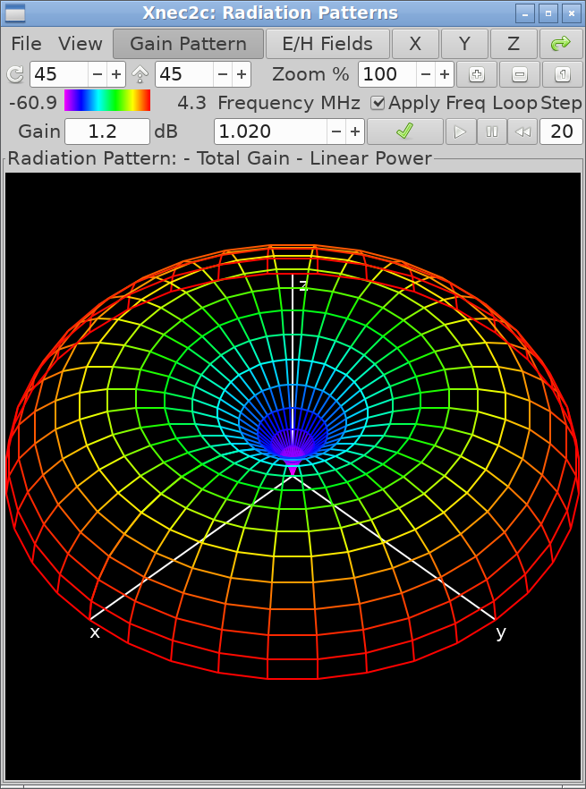
The View menu, in addition to the Common Projection and Common Frequency check buttons, provides sub-menus for selecting Polarization type, Gain Scaling and the Near Field data to be drawn. The selection of polarization type affects the Gain pattern, the displayed Viewer gain and the value of max and min gain as shown to the left and right of the color code bar. The selection of gain scaling only affects the form of the Gain pattern drawing: Linear Power is the most realistic, since the distance from the origin of each point in the gain pattern is proportional to the radiated power density, as is the color code (red for max gain and magenta for min gain). A disadvantage of this scaling is the inadequate representation of side lobes since they are usually significantly weaker than the main beam. Linear Voltage is better in this respect since the position of points in the gain pattern is proportional to Electric field strength and hence follows a square root law. ARRL Style follows a form of logarithmic scaling suggested by the American Radio Relay League, e.g. exp(0.058267 * gain) where gain is in dB10. Finally Logarithmic follows a logarithmic scale with a median of 40dB.
When a Near Field (NE or NH) command is included in the input file, clicking the E/H Field (f) button produces a drawing of the near Electric and/or Magnetic fields. By selecting the Near Field->Poynting Vector menu item the Poynting vector is also drawn. These fields are depicted by lines of fixed length in the direction of the relevant (E/H/Poynting) vector at each point in the drawing. The field strength is depicted by the color of the lines as using the line length for this purpose makes most lines too small to be useful. The drawing of the Near E or H Fields can be enabled or disabled by the Near Field->Near E Field and Near Field->Near H Field menu items.
The Near Field->Animate Dialog menu item opens a dialog box for setting the parameters and starting an Animation of the near field pattern. The Steps/Cycle spin button allows the setting of the number of angular steps around a cycle of the excitation input. The default is 36 and it results in angular steps of 10 degrees. The Animate Frequency spin button specifies a fictitious (slowed down) excitation frequency for which the animation is performed. The default is 1.0 Hz. Clicking the Apply button starts an animation of the near fields using the specified parameters. The OK button does like wise but it closes the animation dialog, while Cancel stops the animation.
The Total Field sub-menu allows the selection of drawing either the Peak value or a "time-frozen" Snapshot of the instantaneous value of the total Near Field E/H vectors. The Snapshot values are calculated as the vector sum of the X, Y, Z components of the E/H field and the Peak values are calculated using the formula NEC4 uses to print the Peak field values.
The Overlay Structure menu item enables the drawing of the structure in the radiation pattern drawing area when the Near Field pattern is selected for drawing. This makes it easier to understand the scale and extend of the Near Field patterns around the structure. The color scheme for the structure becomes white when Overlay is enabled, unless it is overridden by either the Current or Charge distribution being enabled by the relevant buttons in the Main window.
In the second row of widgets, the Color Code bar shows either the max and min values of Gain in the radiation pattern or the maximum value of the field strength in the near E/H field pattern. (Of course only one value can be shown, the precedence being E field, H field or Poynting field strength, depending on which of these is enabled in the View->Near Field sub menu). The Text Entry widget at the right of the color bar shows gain in the direction of the viewer (perpendicular to screen), while the Frequency Spin button following it shows the current frequency in MHz for which data is displayed. It can also be used to enter a new frequency in the same manner as in the Main window. The Redo Check box enables re-calculation and display of data when the frequency value changes, while the button to its right causes same when clicked by the user, but only if a new frequency has been entered.
Currently the Gain pattern is drawn as a transparent wire frame, with each line segment colored according to the average value of gain associated with the two points it joins. The pattern can be "dragged" with the mouse pointer to rotate or tilt it and it can also be positioned using either the X (x), Y (y), Z (z) or Default (d) (right arrow) buttons. The Rotate and Incline spin buttons can also be used to accurately position the Gain pattern in the window. The label in the drawing area's frame gives information on what is on display and also the type of polarization or gain scaling.
Starting with version 2.1, the radiation pattern display can be zoomed in or out by using the mouse wheel or the Zoom controls (Zoom % spin wheel and the + (Ctrl Key +), - (Ctrl Key -) and 1 (Ctrl 1) buttons) and it can also be moved around by dragging with the right mouse button #2.
Both the Gain and Near Field patterns can be saved as PNG image files by using the File->Save (s) or File->Save As (Ctrl s) menu items. The Save option will save the drawings with a suitable default file name which includes a serial number, so that consecutive Saves do not overwrite files, but please note that when xnec2c is restarted the serial numbers are reset so that overwriting will occur if the same input file is opened.
Starting with version 2.1, xnec2c can save the radiation pattern and near E/H field display as a data file for the "gnuplot" plotting program. This is done by using the File->Save As gnuplot menu item, to open a file chooser dialog. If only the stem of the filename is given, xnec2c will automatically add the .gplot extension. Plotting in gnuplot is done with the "splot <filename> with lines" command, although the plot can be enhanced with some of the style etc commands available in gnuplot.
Frequency Data
Plots window:
 The
Frequency Data Plots window is the main display of frequency
related data such as maximum gain, VSWR, input impedance etc. Most
data can be plotted against frequency and some are displayed in
text entry widgets. It is also a convenient way to quickly enter a
new current frequency by clicking on the graph drawing area.
The
Frequency Data Plots window is the main display of frequency
related data such as maximum gain, VSWR, input impedance etc. Most
data can be plotted against frequency and some are displayed in
text entry widgets. It is also a convenient way to quickly enter a
new current frequency by clicking on the graph drawing area.
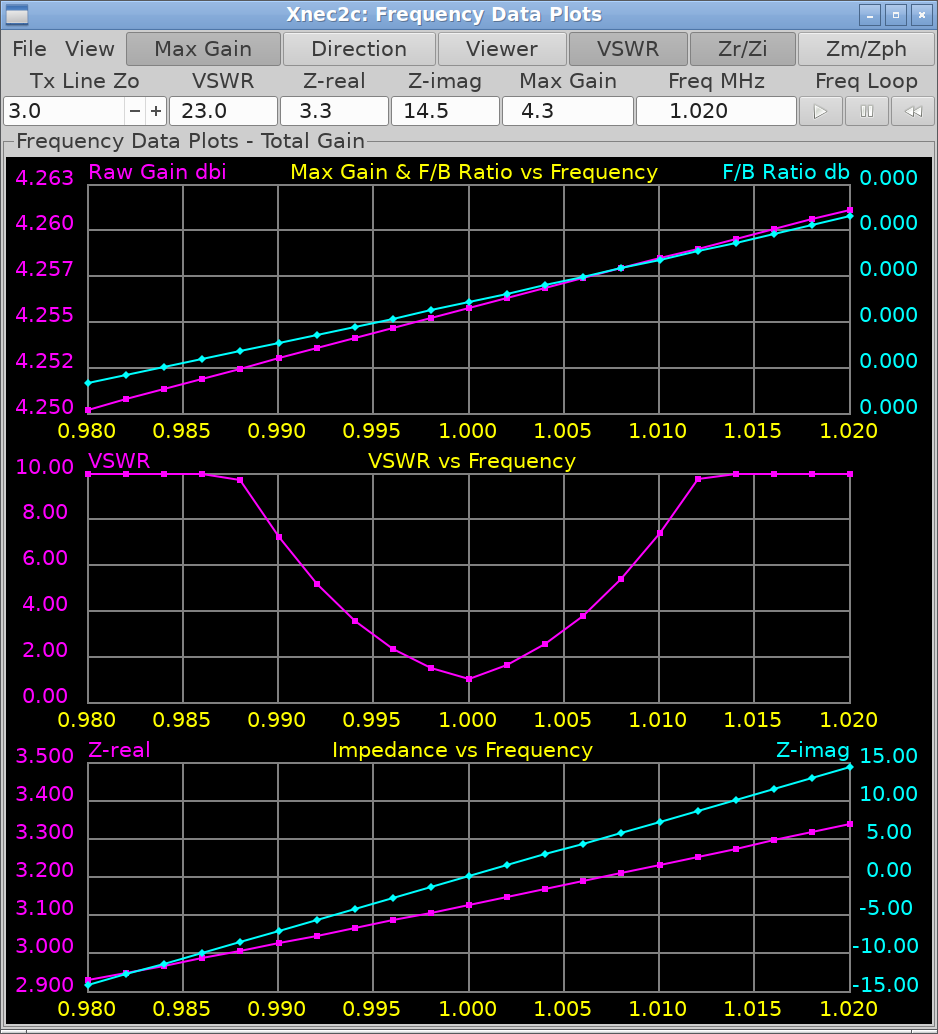
The following applies to all graphs plotted in this window: When a graph of two quantities against frequency is plotted (e.g real and imaginary parts of input impedance), then one quantity is plotted in magenta color and its scale is at the left vertical side of the bounding box. The second quantity is plotted in cyan color and its scale is at the right side while a short descriptive title is printed in yellow at the top horizontal side. The graph bounding box is in white and the scale grid lines are in light gray. When only a single quantity is plotted against frequency, it is plotted in magenta color and the scale is at the left side of the bounding box.
Once graph plotting is complete (e.g. the frequency loop is done), clicking on the graph drawing area with button #1 (left mouse button) will produce a vertical green line in the graph bounding box, marking the new current frequency and triggering a re-calculation of all frequency-related data. Also, displays and drawings in all open windows (assuming the Redo check boxes are ticked active) will be refreshed to present the new data. Clicking on the drawing area with button 3 (right button) sets the frequency to the nearest frequency loop step value, as marked by the little boxes or diamonds on the graphs. However, all the displayed frequency-related data are still recalculated and refreshed e.g. buffered values are not used. Clicking with button 2 (middle button) cancels the green frequency-marking line.
The top row of widgets in this window has at its right buttons
to select data to be plotted against frequency. These are:
Max Gain (m): Maximum gain and front-to-back ratio at each
frequency step.
Direction (d): The direction of maximum gain, e.g. the
radiation angle relative to the xy plane (90-theta) and the phi
angle as defined in NEC2.
Viewer (w): The gain in the viewer's direction, e.g.
perpendicular to the screen.
VSWR (v): The VSWR for the Zo value in the Impedance Spin
button (default 50 Ohm).
Zr/Zi (z): The real and imaginary parts of the input
impedance.
Zm/Zph (p): The scalar magnitude and phase of the input
impedance.
The View->Net Gain menu item changes the second plotted
quantity to the Net Gain of the array. This was added after a
feature request for xnec2c.
The Frequency Loop control buttons at the top right can be use to Start, Pause or Reset the loop. As the loop progresses, more data will be presented in the graphs and in the text entry widgets above the graph drawing area. These widgets display the current frequency in MHz, the maximum gain in the radiation pattern for that frequency, the VSWR for the Zo value in the spin button above and the real and imaginary parts of the input impedance.
The File->Save (s) and File->Save As (Ctrl s) menu items can be used to save the graphs in the drawing area as PNG image files, with a default file name or one of the user's choice respectively. The View->Polarization sub-menu can be used to select the wave polarization type for which data is calculated and presented. When Viewer gain plotting is enabled, the graph will be re-drawn when the structure projection is changed by the various means described earlier (dragging by mouse pointer, Rotate/Incline spin buttons etc).
Starting with version 2.1, xnec2c can save the frequency dependent functions as a data file for the "gnuplot" plotting program. This is done by using the File->Save As gnuplot menu item, to open a file chooser dialog. If only the stem of the filename is given, xnec2c will automatically add the .gplot extension. Plotting in gnuplot is done with the "plot <filename> with lines" command, although the plot can be enhanced with some of the style etc commands available in gnuplot.
NEC2 Input File
Editor:
 Xnec2c has
a built-in NEC2 input file editor to make the edit/save/execute
cycle easier and quicker. The main editor window opens from either
the File->New (n) or File->Edit (e) menu items of the
Main window. The File->New menu
item opens the editor with some default rows ("cards") that amount
to a free space vertical dipole which serves as a simple example.
The File->Edit menu is used to edit a NEC2 input file
that is already open in xnec2c.
Xnec2c has
a built-in NEC2 input file editor to make the edit/save/execute
cycle easier and quicker. The main editor window opens from either
the File->New (n) or File->Edit (e) menu items of the
Main window. The File->New menu
item opens the editor with some default rows ("cards") that amount
to a free space vertical dipole which serves as a simple example.
The File->Edit menu is used to edit a NEC2 input file
that is already open in xnec2c.
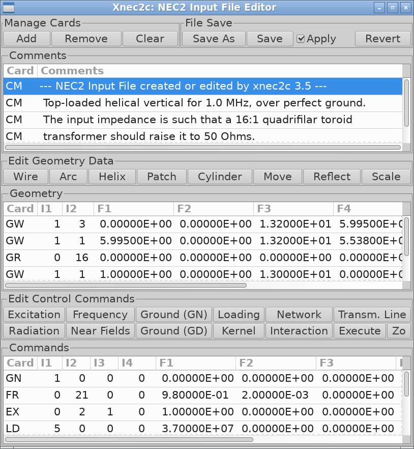
The main NEC2 input file editor can be used to directly edit rows if desired and indeed this is the only method available for editing Comments. The editor though has several dedicated sub-editors for each of the type of card that is indicated in the Buttons above the Geometry and Commands Tree Views. The dedicated editor windows open when these buttons are clicked (to add a new row) or when a selected row is right-clicked by the user with the mouse.
Main Editor Description:
The Main NEC2 Editor window is divided into three Tree View areas,
one for editing Comments, one for editing Geometry and one for
Control Commands. Each tree view has editable rows divided into
cells that correspond to NEC2 input file's card columns e.g. Card
Name (CM) - Comment Text or Card Name (GW) - Wire Data (I1 I2 F1 F2
F3 F4 F5 F6 F7) etc. Each row can be edited by selecting it with a
mouse click and then clicking on a cell. This requires detailed
knowledge of the format of each of the NEC2 input file "cards" and
so this method is only useful for editing comments.
The main editor is controlled by the top row of buttons: The Add (Ctrl-a) button inserts a new blank row in whatever tree view has been selected by a mouse click. The Remove (Ctrl-r) button deletes a row that was selected by a mouse click and the Clear (c) button deletes all rows in a selected tree view and clears it. The Save As (Ctrl S) button opens a file selector dialog for saving the data in the Editor to a NEC2 input file. The Save (Ctrl-s) button writes data in the Editor to an already open input file. The Apply check button, when checked, signals xnec2c to reload the edited input file for execution.
Note: In xnec2c versions earlier than version 2.0-beta, due to the complex file opening process followed by NEC2 (many data sanity checks and initializations etc), reloading the input file resulted in all open windows (radiation pattern, frequency plots) to be closed. This was always an awkward situation and slowed down work in the NEC2 input file editor. As of xnec2c version 2.0-beta, the user interface as well as a fair amount of code in xnec2c, have been modified so that as far as possible, when an edited NEC2 file is saved and reloaded, or another NEC2 file is opened, xnec2c will not close open Radiation Pattern or Frequency Plot windows and will not completely reset internally. This allows the user to edit a NEC2 file in the Editor window and, after saving, to be presented with the new calculations on the structure being modeled.
Finally the Revert (Ctrl r) button reloads the last saved state of the editor from the input file, to reduce the effort needed to recover from a big mistake like clearing a tree view accidentally!
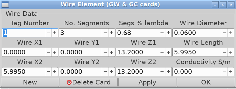
Sample Dedicated Geometry Editor Description:
 Wire
Geometry Editor: This is one of the dedicated "card" or row
editors, for creating or editing wire geometry. It will appear when
the "Wire" button in the "Edit Geometry Data" frame is clicked or
when a selected Wire row is right-clicked with the mouse. In the
former case, a blank "GW" row will be added to the Geometry tree
view which can then be filled by entering wire geometry data in the
Editor and clicking Apply or OK. (in the latter case the editor is
closed). The "Tapered Wire" check button in the upper left corner
opens an additional frame for entering wire taper data and adds a
blank "GC" row to the tree view.
Wire
Geometry Editor: This is one of the dedicated "card" or row
editors, for creating or editing wire geometry. It will appear when
the "Wire" button in the "Edit Geometry Data" frame is clicked or
when a selected Wire row is right-clicked with the mouse. In the
former case, a blank "GW" row will be added to the Geometry tree
view which can then be filled by entering wire geometry data in the
Editor and clicking Apply or OK. (in the latter case the editor is
closed). The "Tapered Wire" check button in the upper left corner
opens an additional frame for entering wire taper data and adds a
blank "GC" row to the tree view.
To make things easier, the Wire editor has spin buttons to specify Length Taper and Diameter Taper separately to hide the need for calculating the actual beginning and end diameters. Also the "Segs % lambda" spin button indicates the wire segment length as a percentage of smallest wavelength and can be use to set the needed number of segments for each wire to maintain a uniform relative segment length for all wires. Please note that this function will only work if the Frequency (FR) card is specified in the Commands tree view and all the data is saved to file and read by xnec2c, so that frequency data is valid in xnec2c's buffers. Please also note that all dedicated editors require wire diameter to be specified but then convert this to radius when entering to the Main editor and saving to file (NEC2 requires wire radius to be specified).
Three geometry Editors (wire, helix, arc) have a spin button to specify wire conductivity in Siemens/meter. When the spin button value is greater than zero, the Editor will enter an LD card in the Commands tree view to specify a type 5 (wire conductivity) loading. This will result in all segments with tag number equal to that in the Editor to be loaded with the specified resistivity. Please note that Deleting the GW row in the Geometry tree view will not remove the LD loading row in the Commands tree view.
All editors (except for the "GE" card) have the following buttons along the bottom of the window: "New" inserts a new blank row in the tree view after entering edited data into the current row. "Delete Card" removes the current row (card) and closes the editor window. "Apply" enters edited data into the current row. "OK" enters edited data into the current row and closes the editor window. Please note that the "GE" row is entered automatically by the first editor used, if the tree view is cleared, and there is no button for it in the Geometry frame. But there is a dedicated editor for it which opens with a right-click on the (selected) GE row and it should be used to specify the presence of Ground (GN command etc).
As of version 3.9-beta, the GH "card" editor has a new
appearance, since the Helix producing code has been edited to allow
the creation of a spiral. Both right-hand/left-hand helices or
spirals can be specified with the radio buttons in the top row of
the GH editor dialog. In the bottom row, the radii that specify the
shape of helices or spirals can be entered in the relevant spin
buttons. These can be linked so that values entered can be
propagated to the right, to make editing easier if all radii are
the same. Right propagation is controlled by clicking on the "chain
link" icons - if the icon displays a linked chain, right
propagation is enabled. Otherwise if a broken link, right
propagation is disabled.
Sample Dedicated Control Editor:
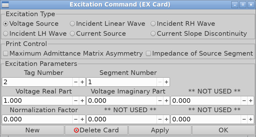 Excitation Command Editor: The Excitation Command
Editor opens when the "Excitation" button in the "Edit Control
Commands" frame is clicked or when a selected "EX" row is
right-clicked with the mouse. The excitation type is selected by
activating the appropriate radio button whereby some labels over
the data input spin buttons will change to indicate their purpose.
The print control check buttons specify additional data to be
printed to the output file but please remember that xnec2c does not
produce an output file. The buttons in the bottom row of the
Command Editors function in the same way as the Wire editor
described above.
Excitation Command Editor: The Excitation Command
Editor opens when the "Excitation" button in the "Edit Control
Commands" frame is clicked or when a selected "EX" row is
right-clicked with the mouse. The excitation type is selected by
activating the appropriate radio button whereby some labels over
the data input spin buttons will change to indicate their purpose.
The print control check buttons specify additional data to be
printed to the output file but please remember that xnec2c does not
produce an output file. The buttons in the bottom row of the
Command Editors function in the same way as the Wire editor
described above.
6. Input File
Considerations:
Since xnec2c is interactive, it will not initiate calculations
without a prompt from the user. For this reason certain NEC2
commands that normally cause execution (e.g. RP, XQ etc) are read
in but not acted upon. Any data in the lines of these commands are
saved for use when the user requests output data calculation and
display, via buttons and menu items in the GUI. Also, since xnec2c
was designed to visualize output data graphically, certain types of
output data requests are not supported (e.g. the surface wave
pattern option (I1=1) of the RP command etc). An error message
dialog will hopefully appear to inform the user of unsupported
commands or options. Here is a list of commands or command options
not supported by xnec2c:
GF: Read Numerical Green's Function: Relevant code has
been removed in nec2c since this type of solution is obsolete.
WG: Write Numerical Green's Function: Relevant code has been
removed in nec2c since this type of solution is obsolete.
NX: Next Structure Data: Relevant code has been removed
since xnec2c cannot operate in batch mode.
PQ, PT, CP: These commands affect printed output and have no
effect on data presented by xnec2c in graphical form. Since version
1.0 xnec2c does not print results to file.
SOMNEC: The separate SOMNEC code has been incorporated in
nec2c and hence in xnec2c also.
EX: When Incident Wave or Elementary Current Source
Excitation is specified, xnec2c can only calculate and render the
re-radiated field, produced by the current induced onto the
structure. Only the initial values of the theta and phi angles are
used and no stepping of these angles is performed. Therefore it is
better to specify only one step for theta and phi in the EX
card.
RP: The surface wave option (I1=1) is not supported.
7. Output File
Considerations:
Printing of results to an output file has been removed starting
from version 1.0, since xnec2c works in a way that does not allow
printing compatible with the NEC2 format. If printing to file is
needed then it is better to use the original NEC2 program, to avoid
bugs that may still be lurking in the C translation.
Version 0.1: First version with ability to draw a color-coded wire frame Radiation Pattern (Near and Far Field), Graphs of various Frequency dependent data (Gain, VSWR, Impedance etc) and the Structure (Wires/Patches), including a color coded Current or Charge distribution.
Version 0.2: Incorporated some changes to the GUI (the Glade-generated design) since after upgrading to GTK+ 2.8.9, the geometry of the windows (the position and extend of buttons/entry widgets) changed a little. Also fixed some bugs in the GUI code to handle unusual sequences of user actions correctly.
Version 0.3: Added the ability to stop the frequency loop by clicking on the frequency display spin buttons and to restart it by toggling the "Gain" or "E/H" buttons in the Radiation Pattern window.
Version 0.4b: Added a NEC2 input file editor that makes the edit/save/reload/execute cycle easier and quicker.
Version 0.5b:Fixed a bug that caused segmentation faults when only one wire segment was present in the structure. This is not a case that will normally exist but the seg fault had to be fixed.
Version 0.6b: Fixed a bug inherited from NEC2: If no geometry cards are present (only a GE card) then there is division by zero in conect(). NEC2 seems to accept the lack of geometry cards, this is now an error condition in xnec2c. Reduced the max value specification of the Capacitance spin button in the Loading card editor, from 1.0e+12 to 1.0e+9 (pF) since the higher value is beyond the range of the "long" type in 32 bit systems. Modified the behavior of some card Editors to make them more user friendly.
Version 0.7b: Fixed a bug in the co-ordinate translation (Move) editor and edited the code in the GW card editor so that the wire diameter does not change when the New button is clicked.
Version 0.8b: Fixed a serious bug that caused segmentation faults and crashes in structures that have a wire in contact with a patch. The subph() routine divides this patch into 3 or 4 sub-patches so the total number of patches increases. There was no provision to reallocate and initialize buffers used in rendering patches in the structure display window. Other minor bugs were also fixed and the example NEC2 files were also checked and edited when needed.
Version 0.9b: Fixed a few bugs mainly in the NEC2 editor code and also changed the code of all individual Geometry and Command editors, so that edited data are set in the main NEC2 editor's tree views when another Geometry or Command card (tree view row) is selected for editing.
Implemented a work round around a serious bug which I could not trace, since it now seems to be outside my code: When the zint() or fbar() functions are called, they seem to corrupt xnec2c's memory allocation when they return. This corruption manifests itself as NAN values appearing in calculations so I modified these functions to return their computed value via a pointer in the argument list. I also changed the function declaration from complex long double to void as it seems this bug is related to functions of the former type declaration, returning a value.
Version 1.0b: In this version xnec2c has been re-worked extensively to make it multi-threading and to streamline its operation to some extend. Many bugs created by these changes, and others that already existed have been fixed, and the user interface has also changed somewhat. The example input files have also been checked and some mistakes in them have been corrected. This is now the first version 1.0 beta release for public testing.
Version 1.0b3: Added setlocale(LC_NUMERIC, "C"); to the main() function, so that in locales where commas are used in decimal numbers xnec2c can read data correctly (suggested by Joop Stakenborg). Some minor changes to the user interface were also made to allow the NEC2 editor window to fit in displays with shorter heights.
Version 1.0b4: After a bug report from Juha Vierinen I changed some "sprintf" commands to "snprintf" to avoid buffer overruns.
Version 1.0b5: Following on the above changes, I revised all similar situations in xnec2c's source and modified all "sprintf" commands to "snprintf" just in case, as I could not replicate the bug so could not test for other similar problems. I also fixed a bug in the "save" and "save as" handler, to avoid false attempts by xnec2c to save structure and radiation pattern/frequency plots pixmaps when a save of the NEC2 editor data failed for some reason.
Version 1.0: After several months with no bug reports or
feature requests, I am sticking my neck out and releasing xnec2c as
version 1.0. This version incorporates the last two feature request
I received from users:
The "Cancel" button on card editors has been replaces with a
"Delete Card" button, which deletes the selected "card" (row in the
NEC2 editor window).
A "Net Gain" menu item has been added to the View menu of the
Frequency Plots window to replace the second plotted quantity with
the Net Gain of the antenna.
Version 1.1: I spoke too soon! A segfault bug has been reported that occurs when Maximum Admittance Matrix Asymmetry printing is requested in the EX card. Although this is not supported in xnec2c, it still produces a segmentation fault because the "ipnt" buffer is not allocated in the netwk() function in network.c
Version 1.2: Made the page size of spin buttons 0 to make setting of spin button values compatible with GTK 2.4
Version 1.3: After an inquiry about using incident field excitation, which was not implemented in previous versions, I removed the restrictions in excitation to allow plotting the re-radiated pattern from a structure excited by incident field or elementary current source. However, the calculations are carried out only for one set of angle-of-incidence angles, e.g. there is no stepping of the theta and phi angles. This would require much more complex changes to xnec2c and I am not currently able to do this.
Version 1.4: Applied a patch supplied by Tom Beierlein, DL1JBE, to fix crashing of xnec2c 1.3 on long input file names (> 80 characters).
Version 1.5: Changed the handling of command line
arguments so that the input file name may be specified without the
use of the -i option. In this case xnec2c will take the last
argument to be the input file name, but only if it has the .nec
extension.
Got rid of some variables that were set but not used, according to
warnings given by gcc.
Applied a patch supplied by Rik van Riel to allow the calculation
of front to back ratios when the antenna is modeled over
ground.
Version 1.6: I received another bug report from Rik van Riel: The patch applied above did not help, as somehow the buggy code got duplicated below the bug fix, reproducing the same error in the calculation of front-to-back ratio! Hopefully fixed this time.
Version 2.0-beta: I received a bug report from David
Binderman regarding an array bounds violation, which he found by
compiling xnec2c with the -D_FORTIFY_SOURCE gcc flag. I fixed this
bug and also tested xnec2c source code using cppcheck.
I decided it was about time I modify the xnec2c user interface so
that it will, as far as possible, allow the user to save and
re-open NEC2 files in the Editor window, without closing the
Radiation Pattern and/or the Frequency Plots windows. This will
significantly speed up work on editing NEC2 files and also make
xnec2c usage less awkward. However, many bugs were introduced and
fixed during this re-write of xnec2c, so users are advised to be
watchful of possible bugs that got away and to report them for
fixing.
Version 2.1-beta: I have introduced many changes in this
version, so I am releasing it again as a public beta version for
testing and bug reports:
After a bug report by David J. Singer, I changed all declarations
of variables that are used in memory allocations, from int to
size_t. This error was in the nec2c code from the beginning but
apparently it only showed up when extremely large memory
allocations are requested in nec2c and xnec2c.
I have replaced all the (deprecated) GDK drawing primitives with
equivalent Cairo graphics equivalents (e.g. replaced
gdk_draw_line() with cairo_line_to()) since Cairo provides for
nicer anti-aliased drawing.
After a feature request by David J. Singer and friend Richard, I
have added code to save data of the structure display, radiation
patterns and frequency plots into file, in a format suitable for
the "gnuplot" plotting program.
Version 2.1: Patched a problem in the graph plotting routines that caused xnec2c to crash with a division by zero fault. This can happen when e.g. a single-wire structure is specified and a plot of gain vs frequency is requested, for a polarization that is at 90 deg to the wire, e.g. requesting gain plot for horizontal polarization for a vertical wire. Since there is no radiation in the horizontal plane of a vertical wire, the values of gain given to the plotting routines are all the same so the vertical scale drawing routines crash xnec2c. Please note that although xnec2c will now not crash as above, the plots will be jumbled and meaningless.
Version 2.2-beta: I made extensive modifications to the source code to silence a large number of warnings generated by the LLVM clang compiler when used with the -Weverything option. These were mostly cases of implicit conversions between variable types, like int to char or uint to int etc. I have also updated the basic files of the GNU Autotools build system, to be compatible with the current version of these tools at the time of writing (February 2013).
Version 2.3-beta: Fixed a bug in the cell_edited_callback() function that caused segmentation fault crashes when a cell in the input file editor was edited directly by the user.
Version 2.4: I submitted xnec2c (and nec2c) for scanning to the Coverity source code audit website, which produced a list of no less than 57 issues to be fixed! Most of them were not bugs that affected calculations but possibly two, both in the Somnec code, one in function rom1() and one in gshank() likely could have caused errors in the relevant calculations. Unfortunately the FORTRAN source of Somnec (as well as that of the NEC2) is very difficult to read so I cannot say with certainty if this was so.
Version 2.5: After a bug report by Jean Collin, I made some changes to the input file parser code in input.c, to properly identify tabs in the input file.
Version 2.6: After a bug report by Lucjan SQ9VPA, I changed the case of the signal handler that deals with SIGCHLD so that it doesn't cause xnec2c to exit when the SIGCHLD signal does not originate from child processes created by xnec2c. It appears that in some Linux installations a SIGCHLD signal is sent to xnec2c even if it is not running forked, e.g. the -j option is not used in the command line.
Version 2.7: After a bug report by Tim, WJ5Q, I fixed a bug that was preventing the creation of an LD card of type 5 (LDTYP=5) when wire conductivity (S/m) was specified in the GW card (Wire) editor. The same bug was present in the GH (Helix) card editor and it was also fixed. I added code so that the wire conductivity for GW, GA and GH cards can be read from the relevant LD card and shown in the Conductivity (S/m) spin button.
After all these changes I checked the xnec2c source code using the Coverity Scan service and I fixed an out-of-bounds read error that was reported by the scanner, in the plot_freqdat.c file.
Version 2.8: Fixed a bug in the GN card editor function which caused xnec2c to save the GN card parameters in the .nec antenna description file without clearing the number of radials to zero. This resulted in the GN card editor window to open with confusing and incorrect defaults for the radial screen, when the Reflection Coefficient Approximation method was selected for specifying ground parameters.
Also fixed some bugs (missing variable initializations) in the Ground Parameters calculation functions which resulted in incorrect Radiation Pattern calculations. This would happen if a .nec file, with Perfect Ground (iperf = 1) specified in the GN card, was opened after a .nec file, with a Radial Ground Screen specified in the GN card, was processed.
Version 2.9: After a request by the Debian maintainer of xnec2c, I added a rudimentary man page he sent me and corrected some spelling errors (arbitrary to arbitrary).
Version 3.0: I have modified the NEC2 file parser so that it can read the file with both the '.' and ',' as decimal point characters. This is necessary to make xnec2c compatible with different locales. I also fixed a resource (memory) leak, reported by valgrind, in the xyz axes drawing routine.
Version 3.1: I have made several changes to the code that
renders wire frame drawings and displays some data, like the
projection parameters (azimuth and elevation of the structure and
the radiation pattern) and gain values. This has resulted in a
faster and smoother animation of these drawings and reduced
workload on the processor during dragging of these images.
I have also reduced the default minimum size of xnec2c's windows,
as I had reports that they would not fit in the displays of some
laptops or monitors, with resolutions on the lower side.
Version 3.2: I made some changes to the Strlcat() function and its usage in the xnec2c code, to improve safe handling of string concatenation operations. Hopefully this has not broken the handling of various strings in xnec2c! ;-)
Version 3.3: I fixed a bug that was in the code that reads the commands from the NEC2 input file, where xnec2c would crash with a segmentation fault when the FR card was after the RP card. Also modified the Strtod() function to avoid freeing the end pointer before it was used, causing problems.
Version 3.4: I fixed a bug in the code that implements the modified GS (scaling) card. In NEC2 the GS card scales all of the structure, but in Xnec2c I modified the code so that it is possible to specify a range of tag numbers to apply scaling to only. When a GS card follows a GX card, selective scaling doesn't work correctly because a symmetric structure is created. If you are using a GS card, it may be better to avoid specifying a tag number range, just in case the bug fix is not complete.
Version 3.5: I modified the NEC2 Editor code so that when
a Geometry or Command editor window is opened, activating Apply or
OK will save data in the editor window to the treeview, even if the
default data is not edited.
I modified the NEC2 Editor code so that if a treeview row is
removed while the relevant editor window is open, then activating
Apply or OK will not attempt to save data to the treeview, since
this will cause an illegal memory access and will crash xnec2c.
Fixed a bug in the Helix editor which caused incorrect calculation
of the segment length as a percentage of wavelength or of the
number of segments/turn that correspond to a given segment length
as a percentage of wavelength.
Version 3.5.1: After a request by Fan Jun BH1SCW, I replaced the original makeshift desktop icon with one provided by Serge ON4AA.
Version 3.6-beta: I migrated Xnec2c to the latest GTK+-3.22 toolkit to bring it up to date. A lot of changes were needed to both the GUI and parts of the Xnec2c source code, mainly the use of GTK3's GUI Builder for creating the User Interface and the revised drawing model of GDK for presenting the Graphics displays. A new autogen.sh script has also been incorporated in the source package and internationalization has been migrated to the GNU GetText system. Because Xnec2c is very complicated and thorough testing is difficult, I am releasing this version as a beta.
Version 3.6.1-beta: After a request by Don Walters W9DKI I modified the xnec2c.glade file to reduce the default size of the drawing areas as they would not fit in displays with reduced resolution. I also removed some legacy code, left over from the migration of xnec2c to GTK3, which was producing error messages from GTK3 during the dragging of structure or radiation pattern displays. And I modified the Makefile.am file to get "make install" to install program files and documentation to the right places.
Version 3.7-beta: After some feature requests by users of
xnec2c, I implemented a number of changes to xnec2c so that it can
save the state of the GUI at exit and restore it on start up. To
this effect xnec2c now produces a configuration file xnec2c.config
in the user's ~/.config directory. In this file xnec2c saves the
state (position, size, active toggle buttons, projection parameters
for structure and radiation pattern displays, the state of the
frequency loop etc) of the main windows, e.g. structure, radiation
pattern, frequency plots and NEC2 editor.
I have also added keyboard accelerators for a number of buttons and
menu items, more commonly used in the main windows of xnec2c, and a
new "Zo" NEC2 "card" to specify transmission line impedance.
Version 3.7.1-beta: Fixed a reported bug that prevented wire diameter entries less than 0.01 in the Helix (GH) card editor. This was due to specifying a minimum value of 0.01 in the xnec2c.glade file.
Version 3.8-beta: I edited some of the code so that when a NEC2 file is saved, the Center x and y offsets (the change of position) of the structure and radiation pattern are not changed. I also arranged for the offset values to be saved in ~/.config/xnec2c.config when closing xnec2c, and to be read back and restored when starting.
Version 3.9-beta: I have arranged for some user actions
to be "nested", mainly regarding the saving of NEC2 editor data
followed by the opening of another file or starting a new project.
Some such functionality already existed in previous versions but it
is now more comprehensive.
Another useful change is fixing a bug in the original NEC2 code for
producing a helix (as specified by the GH "card"). This bug
resulted a division by zero if the helix length was specified as
zero, possibly intended to produce a spiral. The GH card can now be
used to produce both a helix or a spiral with no floating point
exceptions.
Version 3.9: Since I have not received any bug reports for some time after releasing version 3.9-b, and having fixed a bug that resulted in a gtk_widget_destroy() command to be passed on an invalid widget pointer, I am releasing xnec2c as version 3.9.
Version 4.0: I have changed the code that saves the state of the View-Polarization menu items, as it would only correctly save the state of these items in the Main (structure) window. I also changed the code that handles the removal of "card" entries in the NEC2 editor, as it was causing crashes of xnec2c under some user action combinations.
Version 4.0: I corrected some mistakes in the GUI interface code, which handles the creation of windows and dialogs from the glade UI description file. These mistakes were such that they did not effect the operation of xnec2c but in any case I fixed them for the sake of correct programming. Also changed the wire designer dialog to include the Tapered Wire selection check-button in the dialog's frame and the relevant code to deal with this better.
Version 4.1: I corrected some mistakes in the GUI interface code, which handles the creation of windows and dialogs from the glade UI description file. These mistakes were such that they did not effect the operation of xnec2c but in any case I fixed them for the sake of correct programming. Also changed the wire designer dialog to include the Tapered Wire selection check-button in the dialog's frame and the relevant code to deal with this better.
Version 4.1.1: I made a small change to the Radiation Pattern code to allow the drawing of both horizontal an vertical "cuts" in the radiation pattern, in the zx and zy vertical planes and the xy horizontal plane. Also changed the accelerator keys for the Add, Remove, Clear, Save As, Save and Revert buttons to be Modified by the Control button as the original accelerator keys were being activated when writing in the Comments Treeview.
Version 4.1.2: Changed the installation commands in Makefile.am so that all the relevant files (desktop file, application pixmap, configuration file, executable binary etc) are installed under any location specified to the configure script by the --prefix= option. Also modified the program so that on first start up after installation, the application will create its working directory by copying files from the relevant directories under the installation prefix.
Version 4.1.3: Arranged the pipe reading function for the parent process to re-read from the child processes if not all data is transferred at the first read(). In this case xnec2c was crushing with "Resource temporarily unavailable" error message.
Version 4.1.4: Added the stdint.h include file to common.h to fix a compilation error reported by Nick G3VNC.
Version 4.1.5: After an inquiry by Eric Wheeler KJ7LNW regarding the use of the GH card to create spirals, I found a bug that caused the GH editor to delete the GH entry in NEC2 Editor's treeview. I also found a bug that caused the number of turns of a spiral to be rounded to the nearest integer. Both bugs have been fixed in this version.
Further, to aid Eric Wheeler KJ7LNW to develop his Simplex automatic Optimizer, I added code to monitor, with inotify, the .nec input file and to trigger recalculation and plotting of frequency dependent data, while at the same time printing to file results (VSWR, max gain, F/B ratio etc). Also added code so that if the user clicks on the Frequency Plots drawing area, the underlying frequency is saved and re-entered into the frequency-dependent calculations. This, together with maintaining the viewing angle of the Radiation pattern makes it easier to monitor the Optimizer's progress.
Version 4.2: Further to the changes above, I have modified xnec2c so that more than one FR (frequency range) card can be specified in the NEC2 file. This makes it possible to calculate frequency-dependent parameters over separate ranges of interest and thus reduces the time taken by the program to produce results. Unnecessary calculations between ranges of interest are also avoided.
Version 4.2.1: Fixed a bug where the DRAW_ENABLED and PLOT_ENABLED flags where not cleared when the Radiation Pattern Frequency Plots windows were closed. Made extensive style changes to the source code so that resources like #defines, #includes and function prototypes were moved from common.h to the relevant compilation units (.c and .h files).
Version 4.2.2: Fixed a bug in the fbar() in somnec.c reported by Ward Harriman, AE6TY, that caused corrupt results with wire dipoles close to ground and while using Sommerfeld/Norton approximation.
Version 4.2.3: Fixed a bug in Child_Process() in fork.c which resulted in an out-of-bounds (by 1) write to the rc_config.input_file[] character array.
9. Bugs and
Inadequacies:
Xnec2c is based on nec2c, my translation to C of the original
FORTRAN NEC2 code. Any bugs discovered in nec2c will affect xnec2c
as well and they will have to be fixed. In addition, changing the
flow logic of nec2c, from a non-interactive batch-processing
command line tool to a GUI-based interactive application, was
rather complex and introduced many bugs that were fixed, but it is
always possible that a combination of some input file with an
untested sequence of user actions may trigger a hidden bug. Such a
case in fact did appear and it was traced to a bug in the original
NEC2 code. This has been fixed by G. Burke and the fix has been
incorporated in nec2c and xnec2c. See the NEC2-bug.txt file for
details.
When xnec2c was made multi-threading, a lot of bugs appeared and were fixed but again there may be some that have not showed up. One condition that did appear a couple of times was xnec2c getting blocked in a select() call, waiting for a child to write to a pipe. This apparently happened because I was testing a very minimal input file and the child processes seemed to write to the pipes before the parent process dropped into select(). If this seems to happen, do not enable multi-threading (don't use the -j option) for very simple jobs.
A known inadequacy of xnec2c is the slowness of the animation of displayed drawings, e.g. the structure itself, the radiation pattern, near fields pattern etc. Specifically, dragging these drawings with the mouse to rotate or incline them seems very heavy on processor loading, and with most structures the movement is jerky. This is my first attempt at animated wire frame drawings and I lack experience with GTK3 in this field, so I probably went about this the wrong way. I am open to any suggestions that may solve this problem! -;)
10.
Acknowledgment:
Some of the code in xnec2c is based on Pieter-Tjerk de Boer's
"xnecview" application, which visualizes NEC2's input and output
files. The general 'look and feel" of xnec2c was also influenced by
the same application.
Author: Neoklis Kyriazis (Ham Radio call: 5B4AZ)