Recently
I got ICOM IC-R71A receiver from one of
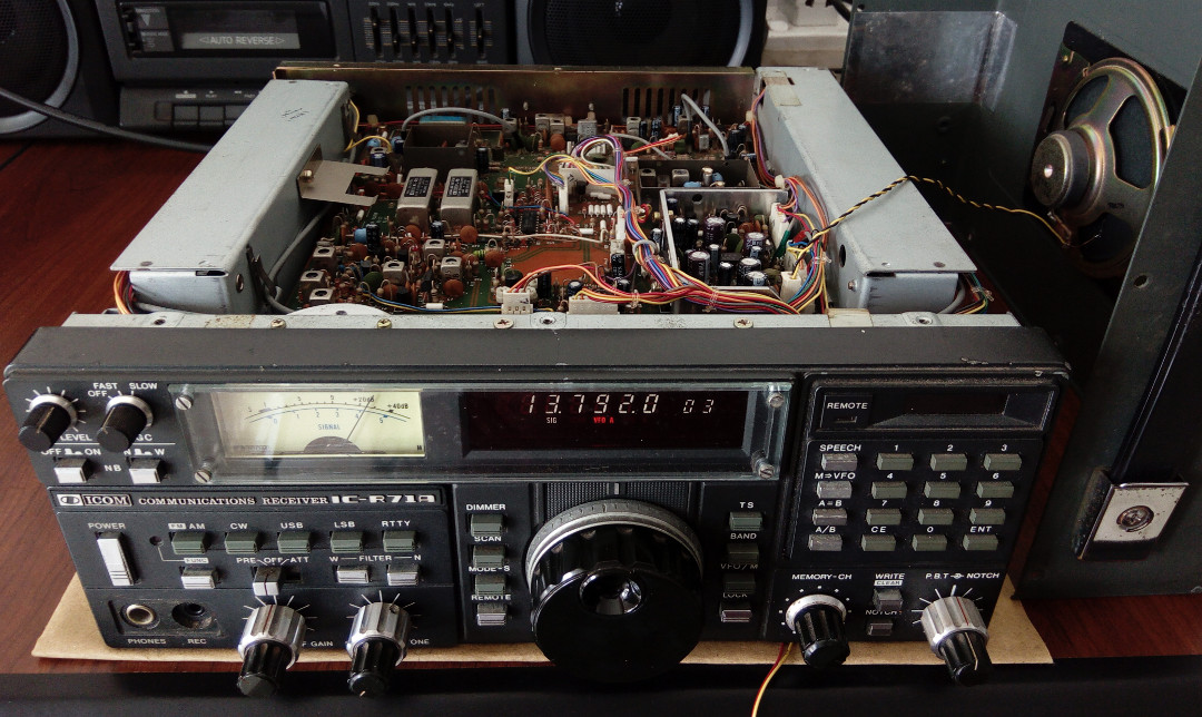
my friend. ICOM IC-R71A is
multi mode quadruple superheterodyne receiver with frequency range from
100kHz to 30MHz. When it comes to my workshop it's completely dead but
outer casing and front panels are in really good condition. Before
troubleshoot the receiver I download both user manual and service
manual from the internet. As like all ICOM
products this receiver also
comes with very detailed user manual and service manual.
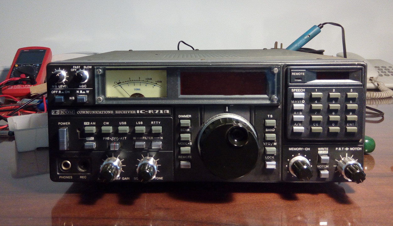
Restored ICOM IC-R71A HF
communication receiver
As I
observed this receiver consist with many PCBs which including:
Main board
Front boards (altogether 7 boards,
which including 1 main board known and matrix board and 6 small PCBs)
PLL board
RF board
Logic board and RAM board
Power supply board
In
addition to above boards there are some spaces in this chassis to
install other optional boards such as FM board.
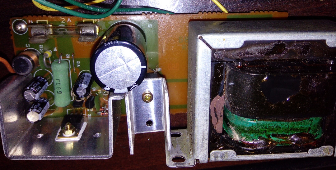
After
observing the power supply board, I notice couple of dry joints in
rectifier module and 2SD880 power transistor. After re-soldering, power
supply
unit starts to work and receiver got powered up.
Restored power supply unit
After
checking it for few minutes I noticed couple of problem with this
receiver. The main issues which I noticed are faulty RF gain controller
and very low audio output from the receiver.
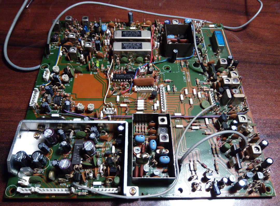
While
checking the boards I notice that most of the electrolytic capacitors
in this unit are in quite bad state. I noticed most of the electrolytic
capacitors in PLL board are in very bad condition and most of them are
in "leaky" state.
After
checking other PCB boards, I decided to recap all the electrolytic
capacitors in this receiver. I bought all necessary capacitors from the
local market and it costs me approximately LKR 300. For most of the
values I choose Nichicon
capacitors because they are commonly available
in local market. For other values I use Panasonic and ELNA
capacitors.
Because 10V capacitors are hard to find I use 16V capacitors instead.
The list of capacitors I replaced are in following list:
Capacitor
Quantity
0.1µf / 50V
4
0.22µf / 50V
2
0.47µf / 50V
9
0.47µf (non-polar) / 50V
1
1µf (non-polar) / 50V
3
2.2µf / 50V
3
3.3µf / 50V
2
4.7µf / 50V
3
100µf / 25V
2
4700µf / 25V
1
1µf / 16V
7
10µf / 16V
7
22µf / 16V
4
33µf / 16V
3
47µf / 16V
21
100µf / 16V
6
220µf / 16V
3
470µf / 16V
6
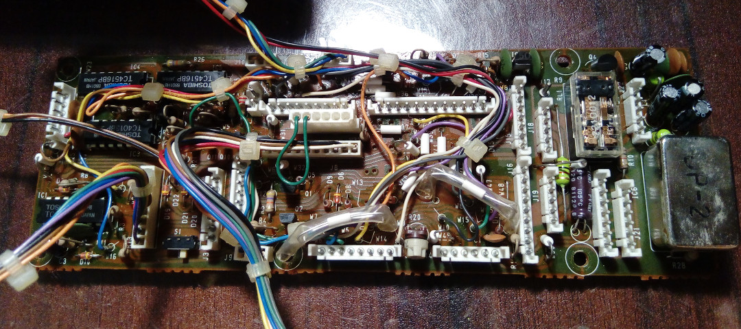
Restored display board PCB
Restored matrix board PCB
It
took me nearly 1 week to replace all the above capacitors.
After
replacing all the capacitors receiver starts to work perfectly and I
got amazed by its performance. Compare with my existing receivers this
receiver performs extremely well and its sensitivity is super
impressive.
Final view of restored
receiver
The
only thing which I cannot restore in this receiver is its S meter lamp.
I try to couple (white) LED into this but it does not work as original
lamp (the dimming functionality seems not working with LEDs), so I
decided to keep it open until I found suitable filament light for this.