| |
1. |
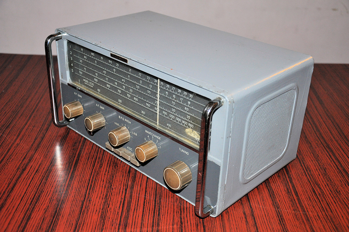
I got schematic of the EC10 MK1 from Eddystone user group. MK2 schematic is also quiet similar to MK1 and major differences between those 2 models are additional fine tuning control and carrier level meter. |
| |
| |
2. |
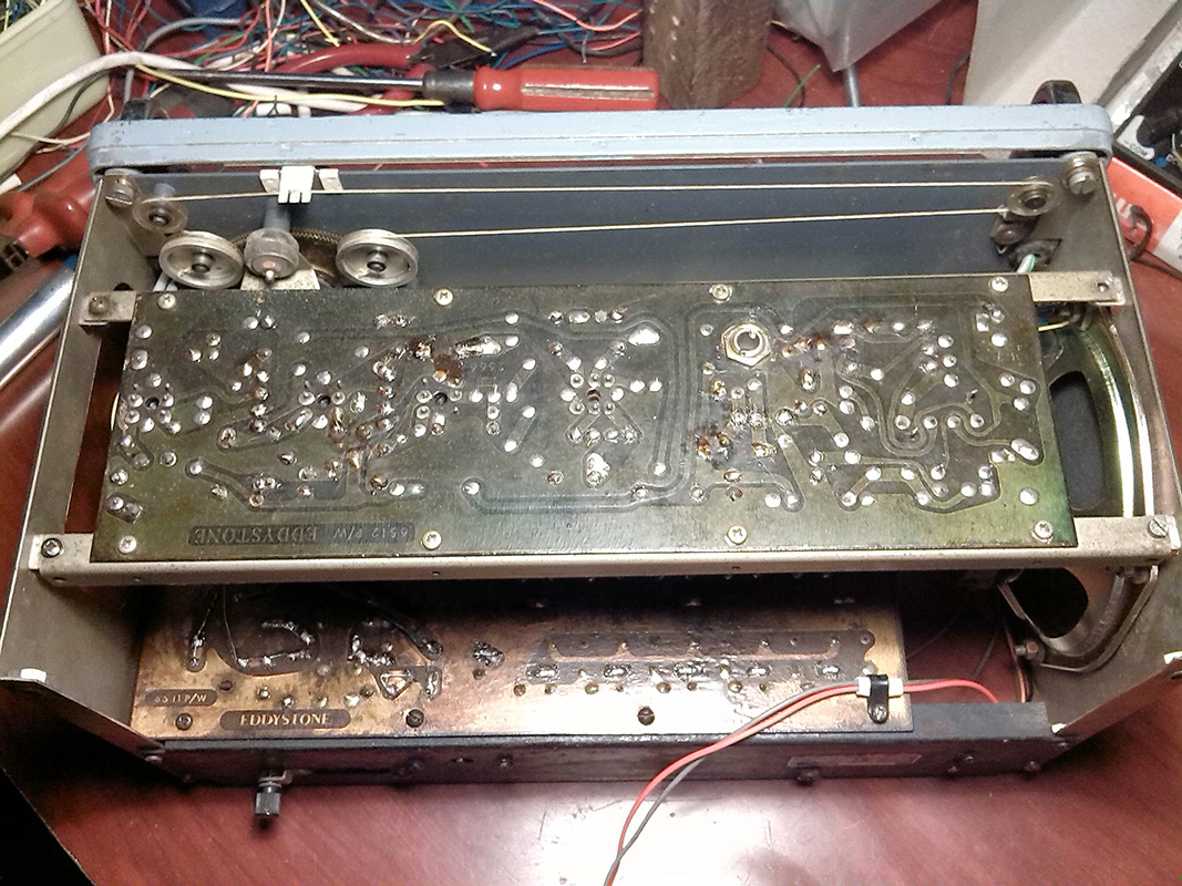
Remove 75% of the capacitors in the receiver and most of them are located in the top PCB (green colored PCB). Capacitors located in the bottom PCB are quiet difficult to remove due to mechanical layout of the unit and channel selector switch need to be disassemble to remove some of the capacitors and resistors. |
| |
| |
|
|
|
 |
|
|
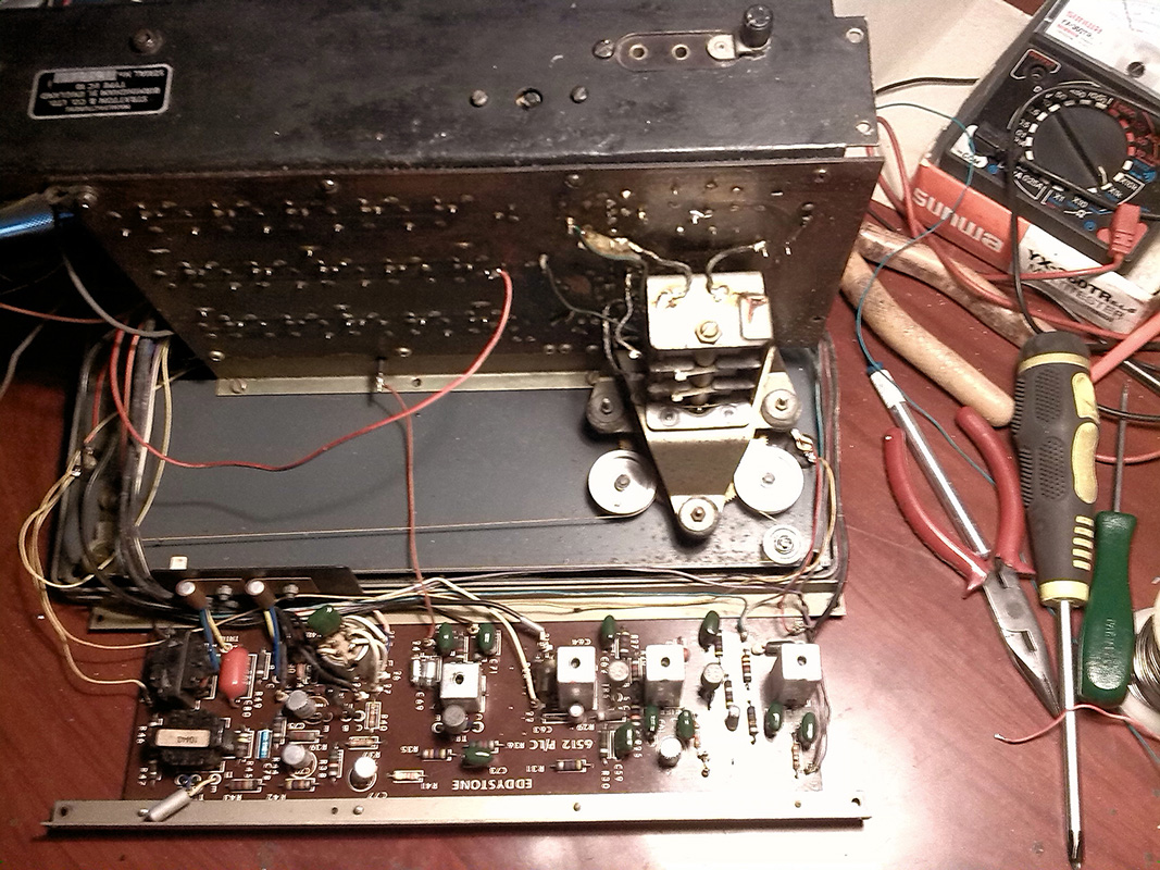
EC10 repairing process on IF and AF amplifier board |
|
|
| |
| |
3. |
I keep all the inductors and trimmer capacitors untouched because all of them are seems fine to me. |
| |
| |
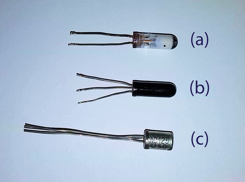
4. |
I replace two OC171 transistors (TR3 and TR5) because of famous tin whiskers effect. In both the transistors I notice short-circuits between Collector and Shield pin. As a solution we can cut down the Shield pin from PCB but I have additional OC171s in my collection so I decided to replace defective transistors with new once. In some sites I notice another solution for this problem. What they suggest is apply some high voltage (via capacitor) to all ECB pins and Shield pin to burn the whiskers. More interesting details related to this problem is found in this forum. |
| |
| |
|
|
|
 |
|
|
(a) damaged OC71 transistor (b) working OC71 transistor (c) AC125 is direct replacement for OC71 |
|
|
| |
| |
5. |
Then I replace OC71 transistor (TR7) because its Base lead is corroded and disconnected. Initially I replace OC71 with new transistor but later I replace it again with AC125 because I have only one OC71 left in my collection and I want to keep it for my other experiments. I didn’t notice any difference between OC71 and AC125 transistor, and both performing equally well. |
| |
| |
6. |
After replacing components in the PCB I start rewiring. I replace all the wires with new wires and organize wire harness as same as older layout. |
| |
| |
|
|
|
 |
|
|
EC10 receiver after rewiring and component replacements. Both the PCBs are covered with protective plastic lacquer. |
|
|
| |
| |
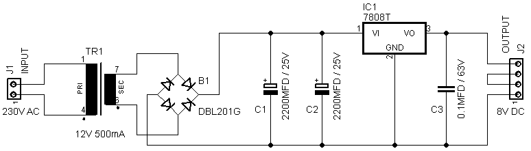
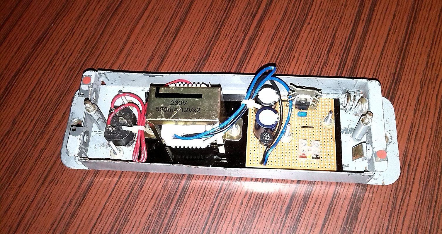
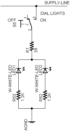
7. |
Both the dial lamps in my EC10 are burned and it is really difficult to fine replacement lamps from our local market. So I decided to use two high bright white LEDs as dial lamps. I connect LED to lamp connections through 1.2K resistor. |
| |
| |
|
|
|
 |
|
|
Wiring diagram for LED base dial light. |
|
|
| |
| |
8. |
I replace existing speaker of EC10 with new 4Ω 12W 5-inch full range speaker. The existing speaker of EC10 is 5inch 3.2Ω but it is little bit difficult to find 3.2Ω 5-inch speakers in local market so I decided to go for 4Ω speaker. |